
Fluke Insulation Testers: Ultimate Guide to Megohmmeters, Testing Methods, and Selection

Professional Insulation Testing with Fluke Instruments
Insulation breakdown is one of the leading causes of electrical equipment failure in industrial environments. Utilizing reliable diagnostic tools ensures long-term operational continuity and protects critical assets. Fluke insulation testers are engineered to deliver noise-free, highly accurate measurements for motors, cables, and switchgear. Whether you are performing routine maintenance or commissioning new installations, professional megohmmeters eliminate guesswork.
Key Benefits of Fluke Insulation Resistance Testers
Modern electrical systems require rigorous safety verification and preventative testing. Fluke instruments combine robust ruggedness with advanced diagnostic features such as Polarization Index (PI) and Dielectric Absorption Ratio (DAR). These capabilities allow technicians to evaluate the aging condition of insulating materials reliably without risking equipment damage.
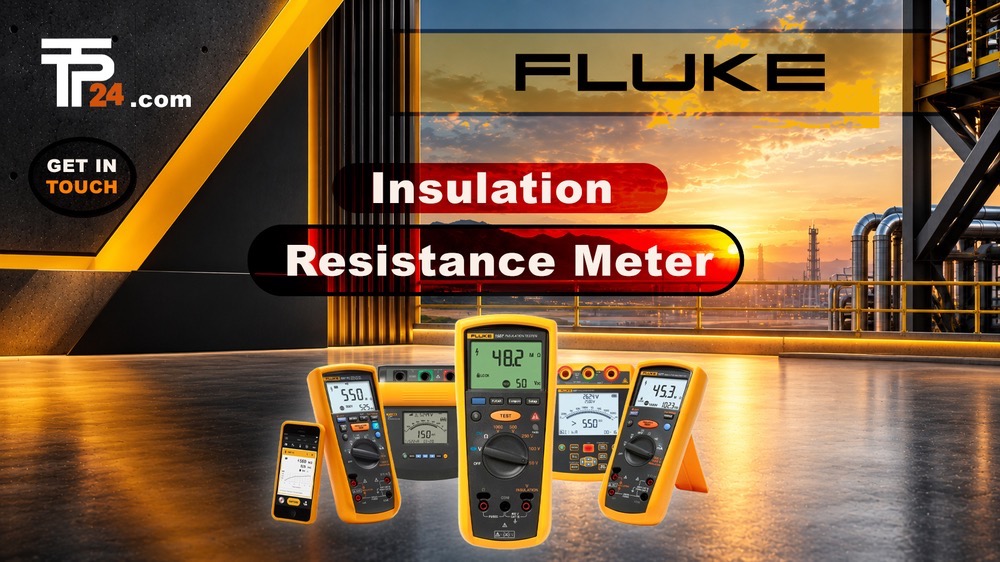
Advanced Diagnostic Features in Fluke 1587 FC and 1550C
The Fluke insulation testers lineup includes versatile 2-in-1 digital multimeters like the Fluke 1587 FC, as well as heavy-duty 5 kV high-voltage testers like the Fluke 1550C. The 1587 FC integrates a full-featured True-RMS digital multimeter with a digital insulation tester, offering wireless connectivity via Fluke Connect. For high-voltage transformers and switchgear, the Fluke 1550C provides selectable test voltages up to 5,000V with measurements extending to 1 TΩ.
Best Practices for Megohmmeter Testing
Before initiating any insulation test, always verify that the circuit is completely de-energized and safely discharged. Connect the test leads securely to the conductors and ground bus. Selecting the correct test voltage prevents over-stressing sensitive components while ensuring compliance with international electrical standards. Regular documentation of test results over time helps engineers predict potential failures before they result in costly unplanned downtime.
Technical Specification Summary Table
| Model | Test Voltages | Max Resistance Range | Safety Rating | Key Feature |
|---|---|---|---|---|
| Fluke 1507 | 50V, 100V, 250V, 500V, 1000V | 10 GΩ | CAT IV 600V | Compact & Rugged Design |
| Fluke 1587 FC | 50V, 100V, 250V, 500V, 1000V | 2 GΩ | CAT III 1000V / CAT IV 600V | True-RMS DMM + Fluke Connect |
| Fluke 1550C | 250V to 5000V (Step-adjustable) | 1 TΩ | CAT III 1000V / CAT IV 600V | High-Voltage 5 kV Testing |
Fluke Insulation Testers: Applications, Features, and Selection Tips
Fluke insulation testers help electrical professionals assess the condition of insulation in motors, cables, transformers, and other electrical equipment. By applying a controlled DC test voltage and measuring insulation resistance, these instruments can help identify deterioration that may not be visible during a routine inspection. Test results should always be interpreted alongside equipment documentation, maintenance history, and applicable safety procedures.
Common Applications for Insulation Testing
Insulation resistance testing is used during commissioning, preventive maintenance, and troubleshooting. Technicians may test motor windings, power cables, switchgear, and electrical installations to check for changes in insulation condition. Recording measurements over time can help maintenance teams identify trends and decide whether additional inspection is needed.
The appropriate test voltage depends on the equipment being tested. Before testing, consult the manufacturer’s instructions and relevant procedures. Do not assume that the highest voltage available on a tester is the right choice for every application.
Features to Compare When Selecting a Tester
When comparing Fluke insulation testers, consider the test-voltage range, resistance-measurement range, display readability, and any additional measurement functions. Some instruments are designed for straightforward insulation checks, while multifunction models can combine insulation testing with other electrical measurements.
Also consider practical details such as test-lead compatibility, data-storage options, portability, and the instrument’s suitability for the work environment. Choose a model based on the tasks technicians perform—not simply on the number of features it offers. Check the manufacturer’s specifications to confirm that the selected tester meets your application’s requirements.
Safe Testing and Record Keeping
Insulation testing should only be carried out by trained personnel. Isolate the equipment from its power source, follow site lockout/tagout procedures, and verify that it is de-energized before connecting the tester. Disconnect sensitive electronic components where required by the equipment manufacturer.
After selecting the recommended test voltage, connect the leads to the specified points and keep clear of exposed conductors while the test is running. When the measurement is complete, allow the equipment to discharge according to the tester’s instructions before disconnecting the leads.
Record the test voltage, measured resistance, equipment identification, date, and relevant conditions. Consistent records make it easier to compare readings over time. A single result should not be treated as a complete diagnosis; follow the manufacturer’s guidance and applicable standards when evaluating the condition of electrical insulation.

Industrial Instrumentation Supplier
Fair Pricing, Guarantee of Authenticity and Quality, Fast Delivery, and Provision of Technical Support to Customers.
Copyright 2025 © TPT24 Company. All right reserved. Powered by TPT24.

