Author: azimitpt

  • Troubleshooting Ripple and Noise in DC Power Supplies

    Troubleshooting Ripple and Noise in DC Power Supplies

    Understanding Ripple and Noise Fundamentals in Power Supplies

    Every engineer tasked with designing or maintaining DC power supplies must grasp the nature of ripple and noise, two factors that critically impact system stability, precision measurement, and overall endurance in industrial electronics. Ripple refers to the residual AC voltage component superimposed on the desired DC output, typically stemming from inadequate filtering or poor rectification performance within the supply’s power stage. Noise, conversely, represents high-frequency interference caused by switching transitions, electromagnetic coupling, or poor grounding schemes that disturb signal integrity across sensitive circuits. Though both manifest as unwanted voltage fluctuations, their origins, spectral characteristics, and mitigation approaches differ significantly. Understanding the physics behind ripple and noise distortion enables engineers to categorize the sources—ranging from diode switching transients, capacitor impedance, and transformer leakage reactance to pulse-width modulation (PWM) switching harmonics—that degrade output precision. In process control systems, laboratory instrumentation, and automotive modules backed by precision DC power sources, maintaining stable output conditions is paramount to ensuring signal fidelity and component longevity. Thus, in-depth knowledge of ripple behavior supports diagnostic accuracy and helps professionals align supply performance with IEC 61010 and EN 55011 compliance norms mandatory for noise suppression in regulated environments.

    Ripple is often characterized by periodic waveform remnants that follow the rectification cycle. In linear supplies, after the AC is converted and filtered by capacitors and inductors, minor charge discharge patterns remain, forming a repetitive oscillation at twice the line frequency. When the filter design lacks adequate capacitance or utilizes components with high ESR (Equivalent Series Resistance), ripple magnitude increases, undermining the precision DC signal required by sensitive analog measurement circuitry. Conversely, in switch-mode supplies, the noise component reflects non-periodic high-frequency spikes caused by rapid transistor commutations and parasitic inductance across circuit traces. These spikes may extend into radio-frequency domains, creating conducted and radiated electromagnetic interference (EMI) that breaches compliance thresholds under CISPR 22 limits. Engineers analyzing power quality use oscilloscopes, spectrum analyzers, and differential voltage probes to quantify both ripple amplitude and noise spectral density, distinguishing mechanical layout-induced disturbances from core electrical instability. Industrial systems powered by high-density DC conversion devices often face ripple coupling across parallel circuits, demanding isolation and shielding practices that form the backbone of reliable electronic infrastructure supported by technology providers like TPT24.

    Both ripple and noise adversely affect high-performance electronics—especially control modules, sensors, and microprocessor-based systems reliant on stable DC rails. Excessive ripple induces reference drift and jitter in analog-to-digital conversions, while transient noise spikes interrupt communication protocols and corrupt firmware data transfers. The cumulative result is erratic operation, premature component wear, and potential compliance violations under ISO 17025 measurement accuracy standards. Therefore, understanding these disturbances not only aids immediate troubleshooting but also informs future design practices for low-noise DC architecture. Engineers tasked with product validation regularly perform ripple rejection testing under variable load conditions, measuring the supply’s ability to suppress AC components while maintaining output regulation. A methodical comprehension of these foundation principles allows professionals to optimize capacitor networks, select effective filtering topologies, and develop tailored diagnostic procedures employing advanced precision tools accessible from TPT24, ensuring that operational stability remains uncompromised across demanding industrial and laboratory environments.

    Identifying Common Ripple and Noise Sources

    The path toward resolving DC power supply ripple and noise begins with correctly identifying each disturbance source along the conversion line. Understanding where unwanted voltage fluctuations arise helps specialists pinpoint root causes that standard insulation tests or visual inspections typically overlook. In unregulated linear designs, ripple primarily stems from rectifier diode switching and insufficient filter capacitor recharge cycles, fostering low-frequency modulation synchronized to the AC mains. In switch-mode power supplies (SMPS), ripple emerges when inductor currents fail to maintain continuous conduction or when MOSFET switching patterns produce uneven energy transfer into secondary networks. Noise sources, however, are multifaceted—ranging from high-frequency coupling through the transformer windings, ground loop resonance, and ambient electromagnetic interference emitted by adjacent circuits. Each condition aggravates signal purity, imposing design inefficiencies and potential damage to precision loads such as sensors or logic controllers. Through advanced testing using high-resolution oscilloscopes and differential measurement probes, maintenance engineers can differentiate ripple frequencies below 1 kHz from random noise bursts extending to MHz ranges. Recognizing the spectral boundary between mechanical ripple and statistical noise provides actionable insight into power conditioning deficiencies or layout flaws affecting system reliability.

    The structural composition of the DC conversion circuit governs where disturbances propagate. Poor grounding leads to uneven potential distribution, while long PCB trace lengths act as unintended antennas radiating high-frequency emissions. A critical yet overlooked contributor to ripple is electrolytic capacitor degradation, where elevated ESR increases ripple amplitude by limiting the effectiveness of charge storage stabilization. Likewise, inductor saturation, insufficient shielding between primary and secondary windings, and high-leakage transformers inject additional harmonic content into the DC line. Engineers routinely employ near-field probes, EMI receivers, and current clamps to trace noise paths through circuit layers, identifying whether interference originates from switching devices or coupling through enclosure seams. For high-performance designs, spatial separation between control logic and power stages is implemented, alongside strategic ferrite bead placement to attenuate high-frequency conduction paths. Testing each noise contributor demands robust diagnostic gear, such as isolated USB oscilloscopes, precision multimeters, and low-noise voltage amplifiers available through TPT24, ensuring technical professionals can map interference at granular levels without compromising signal integrity under high-voltage operating conditions.

    In industrial setups, additional ripple sources manifest beyond internal electronics. External interference from variable-frequency drives (VFDs), motor startup spikes, or grounding asymmetry often couples through shared conductive paths into low-voltage instrumentation supplies. This external contamination produces composite ripple patterns difficult to distinguish from internal defects without comprehensive testing. Engineers must therefore isolate their test bench using shielded enclosures, line filters, and earth isolation transformers to guarantee measurement authenticity. The distinction between conducted and radiated noise is validated via comparative readings under shielded versus unshielded operation. Moreover, environmental humidity and thermal gradients influence component impedance characteristics, modifying ripple propagation properties across time. Recognizing how these external and internal influences interact equips professionals with holistic diagnostic intelligence required for accurate troubleshooting. By systematically characterizing each ripple and noise source from semiconductor behavior to environmental coupling, specialists can apply targeted corrective strategies that uphold stringent performance expectations demanded across transportation, manufacturing, and test instrumentation sectors supported by TPT24’s precision diagnostic portfolio.

    Diagnostic Procedures for Accurate Ripple Measurement

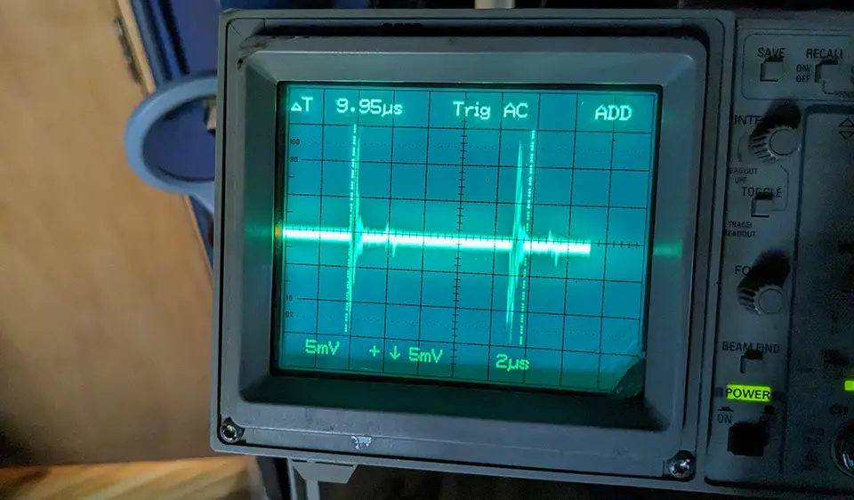
    Comprehensive diagnostic measurement of ripple and noise involves employing instruments capable of detecting minute voltage fluctuations across a broad frequency range while distinguishing true signal artifacts from instrumentation interference. The first step begins with oscilloscope waveform analysis, where engineers observe ripple amplitude superimposed on DC output under varying load conditions. High-bandwidth scopes with differential inputs eliminate ground offset distortion, crucial for verifying actual ripple quantities near millivolt levels. Using low-inductance leads, technicians prevent artificial noise introduction from signal wiring errors that could distort readings. To confirm measurements, simultaneous data capture through spectrum analyzers helps visualize the harmonic distribution across the entire frequency range, revealing whether disturbance energy concentrates at rectification frequencies or within switching harmonics typical of SMPS designs. Complementarily, engineers utilize true-RMS digital multimeters for averaging measurements over longer cycles, confirming amplitude values reported instrumentally. Combining time-domain and frequency-domain verification ensures that recorded ripple values accurately reflect real circuit behavior, satisfying demanding test accuracy standards under IEC 60068 performance qualification protocols frequently applied to industrial DC conversion equipment.

    Proper ripple measurement extends beyond detecting amplitude—it also requires evaluating transient response behavior under sudden load transitions. When a test load changes abruptly, the supply’s voltage control loop may overshoot or oscillate, introducing temporary ripple oversaturation. Engineers induce controlled step changes using programmable electronic loads while logging the supply’s recovery characteristics. These transient ripple data sets help assess controller equilibrium stability and internal compensation network efficiency. Stability assessment ensures that voltage regulation algorithms maintain consistent recovery within microseconds, essential for precision laboratory instruments or automation systems. During monitoring, engineers correlate ripple changes with temperature drift by integrating thermal sensors adjacent to switching elements, confirming that heat variations don’t trigger additional electrical disturbance. Equipment from TPT24, including real-time thermal probes and modular data loggers, assists expertly in correlating electromagnetic and thermal factors for full-scale ripple origin analysis. This multidimensional data review clarifies system resilience against dynamic stress, empowering technicians to predict degradation trends before failures affect operational performance.

    Assessing noise integrity demands meticulous shielding and reference grounding. Engineers establish closed measurement loops with isolation amplifiers and differential probes to remove ground noise that falsely amplifies observed readings. In facilities dealing with high-current DC feeds, stray magnetic fields contaminate measurements through induced voltages on unshielded leads. Mitigation requires coaxial or twisted-pair wiring combined with ferrite suppression cores near instrumentation inputs. The recorded noise spectrum then undergoes statistical averaging to identify deterministic switching spikes versus random interference patterns introduced by environmental factors. For even higher fidelity, professionals employ band‑pass filters allowing selective frequency capture, enhancing spectral clarity during quantification. Diagnostic best practices insist on correlating observed frequencies to known functional sequences—such as PWM switching—confirming whether anomalies represent legitimate system function or unexpected interference. Instruments curated by TPT24 provide the high-accuracy detection capabilities essential to this level of analysis, making it possible for engineers to isolate minute trace distortions without compromising measurement precision or compliance documentation quality demanded across certified testing facilities.

    Mitigation Strategies for Ripple and Noise Reduction

    Minimizing ripple and noise in DC supplies involves combining meticulous design improvements with practical in-field corrective techniques. The most effective prevention starts within circuit architecture: optimizing filtering topologies using multi-stage capacitor‑inductor networks and ensuring proper component selection reduces residual AC from rectification. High-quality low‑ESR capacitors significantly strengthen charge retention capability, flattening output waveforms and diminishing low-frequency ripple inherent in unregulated designs. Complementarily, employing magnetically shielded inductors and ferrite-core transformers curtails radiated fields produced during switching events. Engineers also refine control loop parameters within pulse‑width modulation controllers, adjusting compensation capacitors and feedback resistors to stabilize duty cycles against transients. Fine-tuning these internal elements demands precision testing with high-accuracy multimeters and waveform analyzers, technologies reliably provided by suppliers like TPT24. Successful mitigation transforms unstable supply outputs into precision-regulated DC rails compliant with EN 61000-3-2 harmonic limitations and EMC Class B emission standards, assuring that connected equipment performs flawlessly even under complex industrial loads.

    External ripple control methods address systemic interference beyond circuit boundaries. Power supply enclosures benefit from electromagnetic shielding, using conductive housings and filtered cable entries to suppress radiated emissions. Engineers often add line filters, common‑mode chokes, and feedthrough capacitors at both input and output interfaces to neutralize differential and common‑mode noise returning through external wiring. Implementing star‑ground configurations eliminates circulating currents that cause voltage imbalance between modules. Additionally, isolating sensitive analog boards from switching stages and maintaining trace clearance reduces parasitic conduction paths inside compact SMPS layouts. Maintenance professionals performing troubleshooting should verify each installed filter’s frequency cutoff aligns with observed harmonic bands captured during testing. Utilizing network impedance analyzers available through TPT24’s industrial tools, teams measure attenuation across target frequencies and confirm actual filter efficiency under operational stress. Structural reinforcement like tightening connector termination, cleaning oxidized joints, and replacing aging capacitors complements these electrical strategies, yielding a stable operational envelope where ripple and noise remain below microvolt thresholds required in advanced precision instrumentation.

    Long-term noise suppression integrates preventive maintenance and environmental control to sustain optimal supply performance throughout service life. Regular replacement of high-stress electrolytic capacitors prevents rising ESR, while thermal conditioning inside cabinets limits humidity‑induced dielectric breakdown. Laboratories and production floors implement temperature-controlled ventilation, ensuring stable operating conditions that minimize noise generated from thermally varied component behaviors. Conductive EMI gaskets, bonding straps, and shield continuity inspections maintain enclosure integrity against external disturbances. Engineers also practice cable management to prevent cross-coupling between power and communication lines, reducing stray capacitance that amplifies high-frequency interference. As industrial automation evolves toward higher switching speeds and miniaturized circuit footprints, continuous advancement in ripple mitigation technology becomes indispensable. Through applied innovations such as sinusoidal PWM control schemes, digital compensation algorithms, and adaptive EMI filters, professionals ensure minimal output deviation under load. With access to advanced diagnostic and suppression tools offered by TPT24, maintenance teams sustain benchmark purity in DC distribution networks, guaranteeing fault‑free operation and compliance with rigorous power‑quality specifications required in high-performance control systems worldwide.

    Verification Techniques and Long-Term Performance Testing

    Effective troubleshooting concludes only when ripple and noise performance verification confirms that implemented corrections have produced stable, compliant results under full operational range. Engineers initiate verification by conducting comparative measurements before and after modifications to quantify improvement metrics. Oscilloscope waveform comparison validates ripple amplitude reduction, while spectrum analysis illustrates diminished harmonic intensity across desired frequency bands. To ensure credibility, engineers execute repeated measurements under varied temperature and load profiles using automated data acquisition software that compiles statistically relevant samples. This repetition verifies that smoothing and filtering solutions maintain efficacy throughout normal duty cycles, rather than temporarily masking transients. Testing consistency over extended periods forms part of compliance documentation required under ISO 9001 quality management principles. Instruments from TPT24—including high-precision differential probes and synchronized data loggers—grant technicians the resolution necessary to confirm ripple suppression down to sub‑millivolt levels, marking successful completion of the diagnostic and remediation procedure cycle.

    Once bench validation concludes, field verification ensures that repaired or optimized supplies perform reliably in situ, unaffected by environmental EMI or load variations intrinsic to operational complexes. Engineers deploy portable EMI analyzers and real-time waveform monitors to capture ripple signatures while power systems run live under actual load currents. Comparing lab-controlled data against onsite readings helps authenticate whether design optimizations withstand external interference sources from motors, relays, or communication links. Diagnostic comparison between different facility regions exposes location-based discrepancies, driving infrastructural adjustments like improved grounding schematics or cable shielding retrofits. Technicians frequently perform extended soak testing, monitoring voltage stability over multi-hour sessions to confirm that ripple amplitude remains consistent throughout full operational shifts. Solutions verified through this rigorous multi-environment approach become standard references for best practice, exemplifying professionally executed DC ripple testing workflows. Such systematic validation—supported by robust tools from TPT24—strengthens reliability certification, ensuring every power unit fulfills operational guarantee obligations within industrial energy compliance frameworks.

    The ultimate goal of long-term ripple and noise evaluation lies in developing predictive maintenance insights. By cataloging ripple trends across time, engineers detect capacitor aging, insulation degradation, and feedback loop drift long before output instability jeopardizes production hardware. Continuous monitoring via smart data loggers and AI-assisted condition tracking categorizes fluctuation patterns per unit type, creating a digital health index for each power supply asset. Integration of these indices into enterprise maintenance systems allows managers to schedule component servicing proactively, minimizing unplanned downtime. TPT24’s advanced measurement technology ecosystem supports this continuous assessment model through precision sensors, calibrated instrumentation, and analytics software tailored for predictive diagnostics. Ultimately, long-term ripple verification evolves from a troubleshooting exercise into a sustained operational discipline validating supply integrity against future stress factors. This transformation reduces maintenance expenditure, assures measurement repeatability under regulatory standards, and sustains the flawless DC purity demanded by laboratory, aerospace, and automation sectors relying on meticulously tested and verified DC power supplies as their foundational pillar of electronic reliability.

  • Bench Testing Automotive ECMs: A Step-by-Step Troubleshooting Guide

    Understanding the Purpose of Automotive ECM Bench Testing

    Performing bench testing on automotive ECMs requires deep understanding of how the electronic control module (ECM) functions outside the vehicle environment. The ECM serves as the digital nerve center responsible for processing sensor data, executing logic algorithms, and governing mechanical behavior through precisely timed actuator commands. When removed from a vehicle for diagnostic evaluation, the bench testing setup must replicate critical operating conditions—power, grounding, communication bus interfaces, and simulated sensor inputs—to uncover hidden faults affecting real-time control execution. Engineers conducting such tests aim to verify that voltage references, signal mappings, and logic cycles align with manufacturer specifications under controlled laboratory conditions. This testing circumvents costly on-vehicle experimentation by isolating possible corruption within power drivers, processor timing, or communication registers. With accurate bench testing procedures, professionals are able to assess ECM responsiveness, firmware stability, and component-level health long before reinstalling the module into vehicular system frameworks. Precision instruments—from CAT IV-rated multimeters to automotive oscilloscopes and logic analyzers—are essential tools ensuring that test signals and feedback remain consistent with applicable SAE J2534 and ISO 15765 standards governing electronic diagnostics.

    Understanding the purpose of ECM bench evaluation also underscores the significance of maintaining electronic isolation while simulating behavior across multiple subsystems such as ignition timing, fuel injection sequencing, or emissions control regulation. When the ECM operates on a test bench, its operational environment is recreated through artificial stimulation of sensor channels and controlled power distribution. This process allows technicians to verify internal circuitry—including voltage regulation, pulse-width modulation (PWM) generation, and communication integrity—without external interference from vehicle noise or load variation. Heavy-duty diagnostic infrastructure like programmable power supply analyzers, data acquisition loggers, and signal emulators facilitates the analysis of transient responses within the ECM’s control architecture. Professionals seeking to establish early reliability indicators often monitor how the device handles cold start voltage dips or transient spikes during simulated cranking conditions. These observed behaviors assist in mapping potential weaknesses inside MOSFET arrays, microcontroller cores, or communication line drivers—common culprits behind irregular system performance. Thus, bench testing automotive ECMs remains one of the most controlled and repeatable methods of determining electronic module consistency under laboratory stress parameters, aligning test data integrity with industrial traceability norms.

    Equally important, comprehensive bench testing of ECMs builds technical confidence that firmware calibration, sensor processing logic, and actuator command sequencing are functioning precisely as designed. By disconnecting the module from vehicle electronics and imposing deterministic test scenarios, engineers can isolate each subsystem independently—verifying analog input conversions, digital output states, and event timing accuracy. In this context, ECM troubleshooting becomes a structured scientific process rather than guesswork, practiced within electrical safety boundaries defined by standards like IEC 61010 for instrumentation. Automotive engineers and diagnostic specialists often use reference voltage generators and resistor networks to emulate variable sensors such as throttle position or oxygen feedback units, feeding signals into the ECM while recording output drive responses. When analyzed through oscilloscope waveform inspection, these responses reveal whether signal shaping circuits are stable, output drivers are balanced, and firmware setups correspond correctly to field parameters. The result is a detailed data profile illustrating the ECM’s computational behavior, laying groundwork for corrective calibration or component-level repair when deviations surface. Ultimately, mastering this purpose-driven analytical viewpoint of bench-testing automotive ECMs provides measurable assurance of operational reliability across vehicle populations and defines the precision standard that reputable suppliers like TPT24 uphold when delivering diagnostic and measurement solutions to professional laboratories worldwide.

    Setting Up a Controlled ECM Test Environment

    Creating a precise test environment for automotive ECMs begins with establishing electrical conditions identical to what the module experiences inside the vehicle. Proper setup configuration involves supplying stabilized DC power, ensuring clean ground references, and configuring safety isolation to protect both tester and module from accidental short circuits or voltage escalations. Engineers start by sourcing a regulated automotive power supply rated at 12 V or 24 V, capable of delivering sufficient current while dampening transient surges. This supply connects through fuse protection and current-limiting circuits to emulate ignition-switch activation stages accurately. As part of pre-test verification, technicians confirm voltage output precision using high-resolution digital multimeters offered by benchmark instrumentation providers like TPT24, assuring ±0.01 V tolerance under load simulation. Ground integrity is equally critical: poor grounding during bench testing can distort reference readings, create false fault codes, or trigger erroneous logic execution within the module. Establishing a star-ground configuration reduces ground loop interference, thereby maintaining an electrically neutral framework for all simulated sensor inputs and communication signals critical to accurate ECM evaluation.

    The next stage involves integrating hardware simulators and input stimulus generators that replicate vehicular sensor behavior. Each EMC channel—whether analog, digital, or frequency-based—must reproduce authentic field conditions within controlled laboratory expectations. Engineers utilize signal generators to produce variable outputs simulating crankshaft position, manifold pressure, oxygen level, or throttle feedback. Spread-spectrum signal emulation devices mimic noise and vibration influences observed on real road conditions, enabling stress testing of the ECM’s filtering algorithms. During this stage, technicians fine-tune input scaling by calibrating the generated signal amplitudes against diagnostic thresholds defined in manufacturer documentation. Utilizing instrument-grade components supplied via TPT24, such as precision voltage dividers and low-noise connectors, further enhances measurement fidelity across communication buses including CAN, LIN, and K‑line. This fine-tuned data introduction ensures the ECM encounters realistic signal transitions capable of verifying its capacity to maintain algorithmic consistency while filtering unwanted noise. With all virtual sensors properly aligned, engineers achieve an optimal diagnostic environment that mirrors full vehicle complexity, isolating potential firmware or driver circuit vulnerabilities under tightly regulated laboratory parameters.

    Upon achieving hardware stability, the communication frameworks between the test bench and the ECM require configuration to match industry-standard protocols. CAN bus analyzers, OBD interface modules, and data loggers synchronize operational timing and command exchanges across emulated network traffic. The bench setup for ECM diagnostics mandates defined baud rate alignment—usually 250 kbps or 500 kbps for most automotive CAN networks—and precise termination resistance values near 120 Ω at both ends of the communication line to prevent signal reflections. Engineers monitor bus health through continuous frame analysis, ensuring negligible checksum errors and consistent frame repetition as diagnostic software queries live parameters. When utilizing protocol analysis tools provided by TPT24, test operators can review packet structure integrity, detect timing anomalies, and confirm handshake validity for bidirectional communication. This meticulous synchronization transforms raw bench testing into controlled experimentation capable of verifying firmware communication algorithms alongside hardware transceiver reliability. Such precision guarantees that the bench environment not only tests hardware durability but comprehensively validates data exchange capabilities within real automotive operational expectations—making it the foundation on which successful ECM troubleshooting accuracy rests.

    Performing Step-by-Step ECM Functional Diagnostics

    The cornerstone of bench testing automotive ECMs lies in executing step-by-step functional diagnostics under the safety and accuracy of laboratory conditions. The first stage focuses on power verification, ensuring that regulated supply voltages stabilize across each critical pin before applying operational commands. Engineers measure idle voltage, inrush current, and sustained power delivery using true-RMS multimeters and high-speed data loggers conforming to CAT IV safety standards. This procedure allows identification of load irregularities or short circuits relating to internal regulators and transistor arrays. Once power stability is confirmed, ignition cycle activation follows through simulated key-on and crank sequences, verifying whether the ECM engages startup firmware correctly. During this interval, diagnostic software establishes communication with the module, retrieving baseline operating parameters. The presence of fault codes, delayed processor boot times, or excessive input lag can signal potential firmware or hardware degradation. Utilizing professional-grade tools sourced from TPT24, technicians capture transient voltage spikes and thermal signatures that could expose defective driver ICs or overheated logic gates. These data points represent the earliest indicators of operational inconsistency, serving as benchmarks before advancing into sensor signal analysis.

    Following power validation, technicians proceed to perform signal response testing across primary ECM sensor channels. Analog inputs such as throttle position or oxygen sensor circuits are monitored via dynamic modulations to verify linearity and conversion integrity. Engineers adjust stimulus amplitude and frequency while observing corresponding output waveform changes using digital oscilloscopes or signal waveform analyzers. Stable output curves reflect healthy operational logic, whereas erratic oscillations identify faulty input filters or deteriorated analog-to-digital conversion interfaces. Digital communication lines handling pulse frequency signals—like crankshaft or camshaft synchronization pulses—undergo scrutiny for timing accuracy and phase resolution. Protocol analyzers evaluate whether channel transitions adhere to program sequence within microsecond margins required for precise engine control computations. Each anomaly recorded becomes an actionable diagnostic clue guiding firmware verification or hardware replacement. Employing wave capture systems and diagnostic interfaces distributed through TPT24, specialists accumulate extensive testing datasets that outline electrical behavior per operational phase. These comprehensive results help reconstruct fault trends, empowering accurate troubleshooting of previously undetectable intermittent failures that compromise on-road reliability.

    Finally, actuator output verification forms the decisive step of ECM functional diagnostics. It examines whether control signals directed to injectors, ignition coils, or solenoids respond accurately to software commands under simulated driving sequences. Using high-power resistive loads and relay simulation panels, technicians emulate real mechanical responses to ECM directives. Oscilloscope continuity traces reveal how effectively output stages—often composed of driver transistors or FET arrays—translate logical instructions into stable electrical impulses. Any latency, amplitude fluctuation, or signal asymmetry signifies internal driver circuit fatigue or firmware timing drift. Complementary thermal imaging inspections further highlight localized heat build-up along output channels, directly correlating to component wear phenomena. Tools from TPT24 providing precise temperature logging and time-domain measurement synchronization enhance detection accuracy, ensuring all discrepancies are documented with time-stamped evidence. By meticulously performing this tripartite diagnostic sequence—covering power validation, input verification, and output confirmation—engineers establish an all-encompassing performance profile of the ECM. This structured approach defines the blueprint for successful bench troubleshooting and becomes the gold standard for professional automotive diagnostics worldwide.

    Identifying Common Fault Conditions and Their Causes

    Understanding common failure conditions within automotive ECMs is essential to determine why modules falter during operation or testing. The majority of breakdowns stem from electrical overstress, thermal fatigue, or software corruption events that disrupt synchronized logic execution. Overvoltage exposure caused by defective alternators or faulty jump-start procedures can damage sensitive microcontroller inputs, while prolonged vibration within engine compartments fractures solder joints or connector pins. Thermal stress remains one of the leading contributors to controller degradation, accelerating electrolyte evaporation within capacitors and promoting micro-crack formation in BGA-mounted processors. Engineers examining ECMs on the bench often detect telltale patterns such as burned traces, carbonized driver transistors, or discolored circuit components indicating excessive heat. By employing infrared scanners and advanced thermal cameras distributed by TPT24, technicians visualize uneven heat distribution and discern deteriorating hotspots invisible to standard visual inspection. Detecting these patterns under test conditions allows preemptive corrective measures, extending the functional lifespan of expensive electronic components that comprise the automotive control ecosystem.

    More subtle yet highly destructive are software and data-level faults, often resulting from incomplete flash programming or corrupted memory segments caused by unstable power cycles. Firmware corruption disrupts sensor interpretation and timing calibration, culminating in communication errors that manifest as inconsistent parameter reporting. During bench testing, engineers validate firmware integrity through checksum comparison and bootloader access verification, ensuring the software matrix matches manufacturer-defined reference builds. Specialized diagnostic platforms employing runtime analyzers can emulate execution flow while observing variable changes to confirm algorithmic stability. When anomalies appear—such as looping logic or misaligned data mapping—the ECM is reprogrammed through secure J‑2534 pass‑thru connections supporting standardized vehicle interface protocols. Tools from TPT24 incorporating certified reflash modules facilitate these procedures under controlled laboratory environments, preventing interference or unexpected power fluctuations during code deployment. By rigorously correcting software-level inconsistencies before reinstalling the ECM into operational contexts, technicians avert cascading performance defects across vehicle subsystems dependent on accurate computational precision.

    A third class of fault arises from communication disruption or grounding failure within bench setups or vehicle harnesses. Weak grounding leads to floating voltages that confuse analog sensors and drift digital reference points, while damaged CAN transceiver circuits result in erratic data frames that paralyze network synchronization. Identifying these communication disturbances demands simultaneous monitoring of both electrical continuity and data packet integrity. Using continuity testers, CAN bus oscilloscopes, and ground loop analyzers provided by TPT24, engineers systematically track each circuit from module connector pins to termination resistances. The recorded patterns show whether voltages remain balanced and transmission rates stay within tolerance. Calibration of bus impedance and shield grounding ensures minimal electromagnetic interference across network layers. Once correlation between defective transceiver components and systemic communication skew becomes clear, repair technicians replace or resolder the faulty interface drivers, restoring full data flow consistency. Recognizing these multifaceted failure modes underscores the complexity of automotive ECM troubleshooting, highlighting why qualified laboratories rely on comprehensive bench testing to confirm every fault parameter before reinstating modules into live vehicular systems.

    Optimizing Test Accuracy and Long-Term Reliability

    Achieving enduring accuracy in bench testing automotive ECMs requires both procedural discipline and data management foresight. Every diagnostic event must be conducted according to industry safety and documentation standards to ensure repeatability and traceability. Maintaining test precision demands calibrated instrumentation capable of stable operation under varying power and temperature conditions. Regular instrument calibration according to ISO 17025 guidelines ensures that voltage, current, and timing measurements remain within defined uncertainty limits. Utilizing devices from certified vendors like TPT24, which offer calibration traceability and compliance documentation, strengthens data validity for audit purposes. Technicians must log each measurement phase—including power-up sequences, communication passes, and signal waveform captures—within structured data repositories linking timestamps to module serial identifiers. Automated logging solutions available through data acquisition systems permit full trace review and comparison of successive diagnostic cycles, allowing early detection of statistical deviations. This recorded accuracy transforms individual bench tests from one-time evaluations into cumulative reliability programs that sustain ECM performance consistency across product lifecycles.

    A forward-looking methodology integrates predictive analytics and AI-assisted data processing into ECM diagnostic workflows. As test data volume increases, machine learning algorithms identify subtle correlations between component temperature evolution, voltage drift, and eventual performance degradation. Such analytical models enable maintenance engineers to forecast failure probabilities based on archived bench testing results, implementing preventive recalibration or firmware checks before catastrophic faults arise. Advanced runtime analysis software compiled from TPT24’s diagnostic ecosystem merges sensor simulation data with live waveform behavior to predict electronic stress patterns throughout extended duty cycles. Through continuous data mining, engineers refine quality assurance protocols and improve component design resilience against repetitive stress factors. Implementing these intelligent diagnostic frameworks effectively converts bench testing from reactive troubleshooting into proactive engineering validation—where every module tested not only passes current requirements but also contributes to designing more durable generations of automotive control electronics.

    Sustaining long-term reliability further depends on enforcing environmental control and procedural safety within automated test facilities. Labs must regulate ambient conditions—temperature, humidity, and electromagnetic interference—to guarantee consistent reading accuracy. The ECM bench testing environment should maintain ESD protection through conductive flooring and grounded workstation designs compliant with ANSI/ESD S20.20. Additionally, technicians must follow voltage isolation and PPE requirements during live testing processes, ensuring full alignment with electrical safety mandates under CAT IV rating conditions. All replacement components utilized for ECM restoration must meet OEM specifications verified through traceable documentation. Housing these reliability principles within a well-structured maintenance framework transforms lab performance into an industrial benchmark. Supported by precise, durable instruments and advanced analytic technologies from TPT24, organizations can consolidate their position as leaders in automated diagnostics, guaranteeing enduring reliability and measurement consistency for every bench-tested automotive ECM deployed across modern intelligent transportation networks.

  • How to Diagnose and Test Industrial PLC Control Modules

    Core Principles Governing Industrial PLC Diagnostics

    Before embarking on precise industrial PLC diagnostic procedures, professionals must understand the underlying operational principles that define how programmable logic controllers (PLCs) manage automation systems across industrial environments. A PLC control module operates as the brain of mechanized processes, receiving multiple input signals from sensors and limit switches while issuing output commands to actuators, motors, and control relays. Diagnosing these complex systems involves analyzing electrical integrity, processing consistency, and response timing of the embedded logic. The ultimate goal is to ensure accuracy in signal conversion and continuity between field devices and processor boards. Industrial engineers rely on the ability to characterize voltage levels, current stability, bus communication fidelity, and firmware reliability during diagnostic sessions. When a system anomaly arises, identifying whether the root cause lies within hardware interfacing, wiring faults, or software configuration inside the PLC control module becomes the determining factor guiding effective troubleshooting. Every stage of verification, from power-line inspection to I/O channel validation, draws upon foundational knowledge of IEC 61131 logic architectures, NFPA 70E electrical safety protocols, and equipment compliance under CAT III or CAT IV voltage rating norms frequently applied in industrial automation.

    Understanding how PLC control logic executes its tasks allows the technician to interpret failure symptoms correctly. The processor interprets ladder logic or structured text inputs and converts them into timed electrical pulses controlling actuators. When hardware inconsistencies disrupt this execution—such as erratic voltage readings, missing data packets, or corrupted firmware—the observable outcome manifests as mechanical stalling, relay chatter, or intermittent output behavior. Proper diagnosis therefore requires cross-comparison between the machine’s expected sequence and the actual signal transmission recorded by high-resolution oscilloscopes, logic analyzers, or industrial multichannel data loggers. These instruments, supplied through reliable distributors like TPT24, enable precise visualization of transient behaviors within microsecond intervals. Critical insight into waveform integrity ensures that troubleshooting extends beyond superficial power testing toward deeper functional analysis targeting transistor switching, internal bus communication errors, and microcontroller timing discrepancies fundamental to PLC stability. The holistic diagnostic framework ultimately empowers plant technicians to validate both electrical and logical consistency throughout the automation hierarchy.

    Accurate recognition of PLC module faults emerges from understanding component interaction across tiered architecture levels—namely the power supply subsystem, CPU board, memory section, input/output interface, and external communication ports. Faults manifest through a cascading pattern: voltage drop within the supply leads to processor resets; data corruption in memory generates false outputs; and damaged output drivers propagate inconsistent actuator control. A well-organized diagnostic strategy addresses each layer sequentially to isolate the failure efficiently. Conducting tests using CAT IV-rated multimeters, differential voltage probes, and signal tracing modules provides safe, reproducible insight into circuit responsiveness under operational stress. Equipment from TPT24 designed for precision signal measurement assists specialists in conducting structured electrical analysis compliant with global industrial benchmarks. By mastering these core principles, technicians establish a theoretical and procedural foundation that supports expansive troubleshooting capability, predictive maintenance accuracy, and enhanced durability of industrial PLC control modules across increasingly data-driven production facilities.

    Interpreting Input and Output Signal Integrity

    A major portion of industrial PLC control diagnostics centers around the evaluation of input and output signal integrity. Inputs consist of voltage or current traces representing real-world process data, while outputs deliver electronically executed control instructions. These signals, whether digital or analog, dictate the reliability of an automation sequence. When faults occur—such as floating inputs, grounding errors, or noise-induced voltage drift—the system’s logic misinterprets conditions, resulting in production downtime or unsafe actuator operation. Ensuring precise signal interpretation demands periodic verification using signal tracing equipment, multichannel oscilloscopes, and precision voltage measurement devices. Technicians deploy simulated loads or calibrated sensors to mirror actual field conditions, assessing how accurately the module captures and reproduces signal transitions. Tools supplied by TPT24 allow professionals to record high-frequency variations, measure latency, and compare amplitude deviations that may compromise control accuracy. Recognizing irregular transmission patterns ensures early detection of degraded connectors, faulty isolators, or interference within analog-to-digital conversion pathways—the essential foundation for effective PLC signal diagnosis.

    During testing, each input signal must maintain exact voltage thresholds that meet manufacturer specifications. Low-level current drops or excessive amplitude distortions commonly indicate deteriorated wiring insulation or connector oxidation. In analog configurations, technicians verify linearity through gradual signal variation while monitoring corresponding digital representation inside controller memory using diagnostic software. Digital inputs require confirmation of reproducible ON/OFF state transitions governed by precise timing alignment. When contact bounce or slow edge response introduces discrepancies, maintenance engineers correct the condition through debounce filters or updated input module replacement. The output signals are equally critical; they manifest as relay activations, transistor switching, or PWM sequences driving motor controllers. Using logic analyzers and digital oscilloscopes offered by TPT24, professionals can visualize pulse uniformity, frequency stability, and transient overshoot conditions—all indicative of the controller’s functional competence. Identifying subtle variations at this stage prevents mechanical failures and safeguards electrical components subjected to unpredictable surge effects.

    Noise influence is among the most formidable challenges affecting PLC input/output reliability. Electromagnetic interference from adjacent drives, high-voltage busbars, or rapid switching devices can distort analog readings and digital logic patterns. Mitigation methods include employing shielded cabling, correct grounding topology, differential input conditioning, and specialized ferrite suppression filters. Testing must determine whether the PLC control module successfully rejects common-mode disturbances under full operational load. Engineers utilize EMI diagnostic probes to quantify interference levels and adjust system layout accordingly. Additionally, verifying reference voltage stability across the analog circuitry ensures proper calibration of sensors feeding critical process data. Using high-precision multimeters and waveform recording systems supplied by TPT24, technicians capture consistent benchmarks used to assess the noise immunity of industrial PLCs under adverse conditions. This detailed signal integrity auditing not only reveals potential electronic weaknesses but also enhances design resilience, ensuring that industrial automation lines remain robust against fluctuating environmental and electrical stresses.

    Testing Power and Communication Subsystems Effectively

    Reliable PLC control module performance depends on the stability of its power supply and communication subsystems—two elements that dictate whether logic execution and networked operations can sustain continuous uptime. Power irregularities such as voltage dips, surge fluctuations, or harmonic distortion immediately affect processor synchronization and I/O response. Before conducting complex logic evaluations, maintenance teams must confirm that supply parameters align with rated input specifications. Using true RMS voltage testers, power quality analyzers, and ground resistance meters, technicians can identify transient deviations capable of triggering module resets or data loss. TPT24’s power analysis solutions enable precise logging of event anomalies, tracing back potential causes related to feeder instability or grounding inadequacy. Recognizing that a PLC operates as part of a wider electromagnetic ecosystem, engineers ensure that protective measures—like surge suppression, uninterruptible power supply integration, and isolation transformers—remain functional to prevent cascading power disruptions throughout the industrial control network.

    In parallel, robust communication channel testing validates data integrity between programmable controllers and peripheral equipment. Modern PLC architecture employs protocols such as Modbus, Profibus, Ethernet/IP, and CAN bus, transmitting critical control exchanges that synchronize production lines. Detecting interruptions within these communication frameworks involves monitoring packet timing, signal voltage differential, and bus termination quality. Technicians utilize protocol analyzers to decode and verify message traffic, identifying mismatched frames, checksum failures, or latency spikes that interrupt command flow. Instruments sourced from TPT24 offer tailored software interfaces capable of mapping network topology while pinpointing faulty nodes, damaged connectors, or shielding defects. Proper verification ensures that each transmitted command aligns with the intended logical structure of the PLC program secured under IEC 61158 standards. When communication reliability diminishes, technicians revalidate cable attenuation, connector alignment, and grounding strategy, guaranteeing error-free synchronization necessary for mission-critical applications across manufacturing plants or energy infrastructure.

    Additionally, examining intermodular communication paths strengthens holistic diagnostic coverage. Large-scale systems often involve multiple PLC units exchanging data through distributed I/O networks or fieldbus interfaces. The failure of one communication node can ripple across dependent subsystems, halting coordinated operation. Engineers assess these interconnections with network test tools measuring propagation delay, signal strength consistency, and interference noise ratios. Using intelligent analyzers distributed by TPT24, teams catalog performance statistics, comparing operational metrics under load variation and system idling conditions. This ensures reliable collaboration between controllers and remote I/O terminals even within electromagnetically hostile industrial zones. Managing both electrical power integrity and communication fidelity forms the backbone of successful PLC diagnostics, empowering maintenance professionals to sustain high availability of automated processes that drive manufacturing output and technological efficiency across production ecosystems.

    Advanced Diagnostic Techniques and Field Practices

    Sophisticated PLC diagnostic techniques extend far beyond voltage checks or basic continuity confirmation. Engineers now employ multidisciplinary evaluations combining electrical testing, firmware validation, and real-time simulation to predict module behavior under dynamic workloads. Advanced tools such as in-circuit emulators, runtime analyzers, and machine state monitoring systems enable direct observation of CPU execution and memory utilization. These instruments help pinpoint operational bottlenecks caused by corrupted firmware segments, inconsistent ladder logic definition, or misconfigured timers. Field specialists connect these analyzers to processor interfaces using secure USB or RS‑485 links, enabling code tracing while maintaining safe electrical isolation. Equipment supplied by TPT24 incorporates integrated software that visualizes data flow graphs and I/O transitions synchronized with process activity. By mapping these relationships, engineers identify conditions where logic instruction timing deviates from hardware response—a crucial insight leading to optimized program code and more reliable equipment performance under critical automation loads.

    Another advanced diagnostic approach involves thermal and vibration analysis. Physical degradation within circuit boards often arises from heat concentration or mechanical stress. Excess heat accelerates capacitor aging and destabilizes oscillator circuits crucial to timing accuracy. Detecting these issues requires infrared thermography devices and vibration sensors to analyze component health during operation. TPT24‑certified monitoring systems allow thermal imaging capture with precise resolution, establishing temperature baselines for periodic comparison. Vibration analysis, meanwhile, exposes mechanical resonance affecting connector integrity or component soldering, presenting warnings before electrical discontinuities occur. Combined deployment of these diagnostic modalities translates physical phenomena into preventive data points. Integrating these insights within industrial maintenance schedules backed by software‑linked predictive analytics guarantees predictive reliability—a defining factor separating reactive troubleshooting from proactive asset management. Technicians can therefore secure continuous process uptime by predicting component fatigue long before electrical responses shift beyond regulatory tolerance levels.

    Comprehensive diagnostic practices also encompass firmware and logic validation through simulation testing. Modern PLC programming environments replicate process conditions inside virtualized platforms where logic output and input response can be monitored without risk to physical assets. Such software simulation tools, widely compatible with high‑end analyzers offered by TPT24, allow maintenance teams to conduct structured stress tests confirming whether ladder logic correctly translates sensor information into timed actuator commands. During these simulations, engineers adjust debounce parameters, timing delays, or scaling factors to eliminate runtime discrepancies later observed in production systems. The outcome ensures firmware alignment to real operational dynamics, preserving precise synchronization between digital command processing and analog actuator control. This digital twin testing strategy markedly improves troubleshooting efficiency, as predicted issues appear in simulation long before deployment, reducing costly downtime and accelerating commissioning cycles for sophisticated automation platforms dependent on PLC control modules for stability across large‑scale industrial processes.

    Preventive Maintenance Strategies for Long-Term Reliability

    The culmination of successful industrial PLC testing lies in establishing structured preventive maintenance strategies designed to preserve long-term reliability across control infrastructures. Automation facilities operating around the clock cannot afford sporadic shutdowns due to avoidable circuit fatigue or misconfiguration. Designing maintenance schedules requires detailed recordkeeping of electrical measurements, firmware revisions, thermal trends, and hysteresis data documented after each diagnostic session. By integrating outcome logs into centralized maintenance software accessible via cloud-enabled monitoring platforms, engineers gain predictive visibility into component degradation patterns. Instruments provided by TPT24, featuring digital data logging and wireless connectivity, bridge on-site metric gathering with enterprise-level analytical dashboards, promoting response optimization before critical threshold violations occur. This accessibility underpins proactive servicing, allowing decision-makers to coordinate timely module replacements, firmware updates, and calibration routines minimizing expensive downtime across interconnected automation ecosystems.

    Training personnel in advanced PLC signal verification procedures remains equally essential for ensuring preventive effectiveness. Technicians must understand interpretation nuances regarding voltage fluctuations, timing jitter, and bandwidth limitations typical of aging circuitry. Workshops focusing on signal analysis, power quality assurance, and communication protocol integrity expand organizational knowledge bases, empowering maintenance teams to act decisively during early fault detection. Adoption of TPT24’s diagnostic training kits, encompassing field-calibrated multimeters, pulse recorders, and real-time analyzers, enhances technician capability to perform standardized verification tasks under variable environmental conditions. Knowledge reinforcement through ongoing practice translates technical familiarity into expertise, resulting in fewer misdiagnosed signals and better maintenance execution. Building such procedural expertise solidifies the network’s operational resilience, ensuring that programmable controllers deliver optimal process accuracy and safety compliance demanded in industrial power, manufacturing, and chemical automation domains.

    Finally, preventive maintenance efficiency is tied to systematic documentation and benchmarking routines. Recording each diagnostic measurement, comparing successive test results, and classifying deviations under specific operating conditions generate traceable reliability indices for every PLC control module deployed. Standardized record formats align data interpretation with international norms like ISO 50001 and IEC 60364, ensuring analytical coherence during audits or compliance assessments. When integrated with digital asset management platforms, these datasets fuel machine‑learning‑based predictive algorithms that preempt failure probability before symptoms manifest physically. Utilizing TPT24 logged measurement data, companies leverage curated insights to refine maintenance intervals while extending hardware longevity across generations of installed controllers. Through consistent benchmarking and disciplined measurement recording, maintenance organizations convert diagnostic evidence into performance intelligence. That cycle of continuous auditing, training, and digital data application transforms reactive hardware testing into a scientifically grounded sustainability program aimed squarely at safeguarding the enduring reliability of industrial PLC control modules operating within globally competitive, high-efficiency industrial infrastructures.

  • Understanding Input/Output Signals for Control Module Verification

    Fundamental Concepts Behind Input Output Signaling

    Modern industrial automation relies on the precise exchange of input/output signals to maintain synchronization between sensors, actuators, and the electronic control modules (ECMs) that regulate system performance. Understanding these signal pathways is essential for engineers and technicians responsible for diagnostic verification, equipment commissioning, and troubleshooting complex automation frameworks. In any control module, the input channels serve as data receivers—collecting parameters such as voltage, current, pressure, temperature, or motion—from field sensors. Conversely, output channels function as data transmitters that forward processed instructions to operating components like solenoids, relays, or drives. When an ECM experiences communication errors, voltage mismatches, or timing discrepancies, diagnosing signal continuity and distortion becomes a priority for maintenance teams. Industrial testers and verification instruments supplied by TPT24 allow professionals to detect anomalies in digital and analog transmission lines, ensuring that power electronics and logic circuits adhere to operational accuracy defined by IEC 61010 and IEC 61131 standards for programmable controllers.

    The precise integrity of input/output signals determines whether an industrial system operates safely, efficiently, and predictably under varying load conditions. Industrial controllers convert analog measurements into binary information that the internal processor can interpret. If the voltage amplitude or signal polarity deviates from specification, the control algorithm may miscalculate actuator response, triggering mechanical errors or protective shutdowns. The line noise associated with electromagnetic interference (EMI), ground loops, or cable shielding faults contributes significantly to signal degradation. Therefore, effective signal verification requires the combined measurement of amplitude stability, timing consistency, and impedance conformity across all terminal connections. Multifunction data acquisition loggers, oscilloscopes, and logic analyzers available through TPT24 enable comprehensive signal audits in real time. By capturing transient voltage behavior, dips, or latency variations, reliability engineers gain quantitative insight into functional health, preventing systemic failure across automated networks operating in high‑stress production environments.

    The operational framework of any control module verification procedure starts with defining the signal expected through its designated terminals. Each terminal group corresponds to specific communication types—digital discrete inputs, analog sensor feedback, or pulse‑width modulation outputs—forming a mapped architecture of the module’s control functions. During verification, technicians simulate real‑world operating conditions by generating controlled signals, ensuring each channel responds predictably. The measurement of feedback signals, isolation resistance, and electrical noise levels confirms that logic circuits meet tolerance criteria. In environments such as automotive diagnostics, process instrumentation, or robotic servo control, mastering signal verification principles provides unparalleled accuracy and confidence in safety certification. TPT24’s precision testing devices, equipped with digital filters and adaptive bandwidth selection, allow users to validate both static and dynamic conditions without introducing secondary interference. Understanding these fundamental concepts underpins accurate control module performance assessment across any industrial domain where downtime equates to substantial financial loss.

    Signal Types and Their Functional Behavior

    Control module verification requires familiarity with multiple categories of input/output signals—namely analog signals, digital signals, and pulse‑based control signals, each exhibiting distinctive transmission and feedback characteristics. Analog signals typically represent continuous values such as temperature, pressure, or level, converted by sensors into variable voltage or current channels like 0–10 V or 4–20 mA ranges. Digital signals operate through high/low logic states that correspond to discrete ON/OFF events. Pulse‑based signals, often utilizing PWM (Pulse Width Modulation), regulate proportional output to servo motors or throttling valves through timed voltage transitions. Recognizing these signal modalities allows technicians to match testing instruments with specific verification demands—whether validating sensor calibration or actuator response cycles. Industrial test solutions from TPT24 integrate multiple measurement functions, enabling calibration of analog amplitude, verification of digital state accuracy, and analysis of pulse duty cycles from a single portable platform. Such integration simplifies laboratory and field procedures, ensuring consistent diagnostics across automation architectures.

    The electrical behavior of analog signal lines is sensitive to impedance mismatch, grounding irregularities, and inductive coupling with adjacent circuits. When an analog channel becomes unstable due to cable deterioration or connector corrosion, noise manifests as erratic sensor readings or inconsistent module response. To verify analog line integrity, technicians measure linearity and resolution accuracy between source and processor using high‑resolution multimeters and oscilloscope waveform comparison techniques. Proper shielding and grounding reduce interference, while differential input designs mitigate common‑mode noise. During verification, engineers employ simulated signal generators to replicate sensor activity, observing module reaction under controlled conditions. Analog analysis therefore reveals how precisely the control module’s analog‑to‑digital converter (ADC) operates over time, identifying software configuration errors, drift in reference voltages, or component fatigue. Field‑ready analyzers distributed by TPT24 supply robust isolation up to CAT IV 1000 V, guaranteeing safe measurement even under variable industrial energy exposures.

    Digital and PWM signals necessitate measurement techniques emphasizing timing accuracy and pulse integrity rather than linearity. Digital logic lines communicate discrete transitions that must occur within microsecond tolerance to avoid synchronization faults. PWM signals adjust frequency or duty cycle proportionally, commanding output modulation to achieve variable responses in actuators or motor controllers. Testing requires instruments capable of high‑frequency sampling and precise edge detection, ensuring the circuit maintains commanded timing. Verification of digital outputs includes monitoring propagation delay and logic threshold adherence across microcontroller pins. Engineers use logic analyzers, protocol decoders, and digital oscilloscopes—available through TPT24—to validate binary transitions and detect anomalies like stuck bits, ghost pulses, or timing drift. Mastery of these signal behaviors ensures reliable execution of control algorithms within automated systems, helping industries maintain performance efficiency aligned with ISO 50001 standards governing energy and process optimization.

    Diagnostic Testing and Measurement Methodology

    Comprehensive control module verification relies on structured diagnostic testing protocols combining visual inspection, electrical validation, and dynamic functional analysis. Technicians begin by evaluating wiring layouts, connector conditions, and grounding continuity before introducing test signals to the input/output ports. Each measurement distinguishes electronic deviation from mechanical interference using controlled reference instruments. Industry professionals employ signal simulators, precision multimeters, and portable data loggers to test analog and digital reactions across networked modules. Measurements determine whether each input channel correctly detects expected voltage or current values while output channels deliver proportional responses. This step isolates false positives caused by defective sensors or modules. For automated verification, TPT24 provides multifunction diagnostic units equipped with programmable signal output and internal memory storage designed to replicate operational patterns over extended durations, enabling long‑term monitoring of transient or intermittent failures within complex automation systems.

    Electrical verification in module testing goes beyond simple continuity assessment. Engineers measure voltage offset, power consumption, current leakage, and frequency accuracy. Signal variability, harmonics, and noise must all remain within permissible thresholds to confirm module integrity. When anomalies arise—such as high ripple content or phase distortion—technicians trace underlying causes using advanced equipment capable of dynamic response analysis. This includes identifying poor solder joints, degraded capacitors, or firmware instability that alter communication precision. High‑bandwidth digital oscilloscopes and electronic load analyzers, obtainable through TPT24, support these functions by registering continuity and reactivity to simulated real‑world operations. Professionals can correlate waveform consistency with control logic performance, ensuring that both electrical and software systems conform to operational expectations dictated by industrial regulatory standards such as IEC 61131‑2 for programmable control equipment requirements. Verifying correct electrical performance guarantees downstream process reliability and safeguards personnel during device replacement or commissioning.

    In functional testing scenarios, verifying signal response timing and synchronization across linked control modules determines crucial system stability metrics. The delay between sensor input and actuator output defines how efficiently a process executes. Excessive lag may indicate firmware bottlenecks, bus communication interference, or defective timing crystals within electronic boards. Professionals utilize time‑domain analysis tools and protocol analyzers from TPT24 to measure latency and serial bus behavior in applications employing CAN, Modbus, or RS‑485 networks. Through synchronized measurement, engineers discern inter‑module harmony and signal order execution required for coordinated motion or temperature control loops. Diagnostic methodology therefore encompasses electrical and software verification under diverse conditions, providing comprehensive insight into system health before reinstating full operational load. Applied rigor at this stage mitigates downtime and supports predictive maintenance customization based on statistically observed trends across multiple detection cycles monitored by advanced electronic instrumentation.

    Common Verification Challenges and Preventive Solutions

    Testing and verification of input/output signals introduce multiple technical challenges that complicate diagnostic accuracy, often resulting in misinterpretation or data distortion. Common obstacles include electromagnetic interference from nearby power equipment, unstable grounding creating current loops, and fluctuating supply voltage influencing signal reference levels. EMI may arise from motor drives, welding equipment, or frequency converters operating in proximity to the control network. These disturbances contaminate both analog and digital lines, causing erratic meter readings or software miscalculations. Professional testing requires shielded cables, twisted pair connections, and adherence to proper routing distances between power and signal lines. Using EMI‑resistant measurement devices such as differential probes or high‑impedance voltage testers—offered by TPT24—helps engineers acquire clean data unaffected by noise. Introducing ferrite cores and ground isolation further stabilizes line integrity, transforming unstable signals into readable waveforms for accurate control module verification across electrically dense installations.

    Ground faults, weak insulation, and connector corrosion remain leading causes of signal transmission distortion during module testing. Over time, environmental exposure degrades terminal contact surfaces, creating variable resistance along the signal path. These irregularities alter measured voltages, leading to misalignment between programmed threshold values and observed feedback under calibration. Preventive measures include periodic inspection of connectors, ensuring torque‑correct fastening and applying contact resistance testers for validation. Industrial analyzers from TPT24 integrate automated measurement logging for long‑term stability assessment, enabling predictive maintenance scheduling across control networks. Additionally, technicians must maintain insulation ratings in conformity with CAT III and CAT IV classifications when operating under elevated system voltages common in hybrid installations. Routine resistance benchmarking and moisture prevention protocols ensure lasting signal reliability, protecting module logic integrity and guaranteeing sustained electrical performance during mission‑critical operations.

    Temperature, humidity, and vibration present environmental hazards influencing signal distortion and component fatigue. Thermal expansion impacts connector tension, while vibration weakens solder points or PCB mounting structures. Monitoring environmental influence during signal verification helps correlate mechanical dynamics with electrical responses, revealing potential early failure trends. Engineers apply temperature dataloggers, vibration analyzers, and infrared thermography tools to capture thermal and mechanical signatures integral to complete module evaluation. TPT24’s environmental monitoring kits track these external variables alongside electrical parameters, supporting unified maintenance analysis. Stabilizing ambient conditions—through proper cable insulation, temperature control, and structural reinforcement—reduces reactive measurement drift. Preventive solutions combining electrical and environmental diagnostics empower engineering teams to preserve control integrity over extended service periods. Recognizing and managing these factors builds resilient automation networks, reinforcing both signal precision and longevity of electronic control module infrastructure throughout industrial systems.

    Integrating Advanced Tools for Module Validation

    Next‑generation instrumentation for control module verification emphasizes automation, data integration, and AI‑assisted predictive analytics. Modern maintenance workflows increasingly rely on networked instruments capable of remote data capture and real‑time cloud synchronization. By stitching continuous electrical measurements with environmental metrics, engineers construct performance profiles detailing signal drift, latency, and transient behavior under varying field conditions. Intelligent diagnostic equipment available through TPT24 incorporates built‑in algorithms that compare current readings against historical baselines to highlight deviation patterns indicative of component fatigue or near‑threshold voltage instability. Integrating these tools within industrial IoT ecosystems transforms traditional testing into continuous reliability monitoring, enabling predictive asset management compliant with contemporary ISO standards. Such advancements redefine module verification from isolated measurement procedures into interconnected diagnostic frameworks leveraging analytics for preventive decision‑making and supply chain optimization.

    Digitalization of testing methodology also allows standardized reporting through software‑based calibration management systems. Engineers can simultaneously manage test schedules, export measurement results, and track calibration validity across multi‑site operations. Automated documentation accelerates compliance with international directives such as ISO 17025 laboratory accreditation, assuring traceability of all electrical data collected during control module verification. Portable computer‑linked testers offered by TPT24 utilize USB connectivity and embedded datalogging software that auto‑compiles voltage trends, signal quality ratios, and timing graphs into secure archival formats. Although no tables or charts appear in textual reports, this structured record maintaining philosophy enhances audit readiness and process transparency across industrial automation facilities. Embedding comprehensive instrumentation within verification routines bridges the gap between traditional analog practices and digitally driven precision engineering vital in complex production ecosystems where accuracy dictates profitability.

    The future scope of input/output signal verification integrates sensor fusion and machine learning procedures to automate fault identification without constant human interpretation. AI algorithms analyze waveform signatures, recognizing deviations indicative of EMC interference, ground faults, or logic timing failure faster than manual examination methods. Coupled with cloud‑enabled diagnostic hardware, these intelligent platforms provide predictive maintenance recommendations and inventory alerts for spare module replacements. TPT24’s portfolio of advanced analyzers and signal testers remains adaptable to such evolving technologies, supporting connectivity upgrades, software integration, and sustainability metrics essential for data‑driven industries. As control modules become increasingly intelligent, verifying their signals demands equal sophistication in testing technique—combining electrical precision, analytical depth, and procedural consistency to ensure enduring reliability. Mastering this integration equips engineers to uphold optimal functionality across interconnected automation frameworks, establishing signal verification as a pillar of industrial safety, efficiency, and technological progress worldwide.

  • Common Failure Signs in Electronic Control Modules and How to Test for Them

    Understanding the Role of Electronic Control Modules

    In every advanced industrial system or heavy‑duty machinery configuration, the electronic control module (ECM) operates as the central intelligence that monitors, interprets, and adjusts electrical and mechanical functions in real time. Whether integrated into automated manufacturing lines, HVAC systems, or vehicle powertrains, the ECM coordinates multiple sensor inputs and actuator outputs while maintaining precise voltage regulation and operational efficiency. The importance of this module lies in its computational ability to handle complex algorithms controlling fuel injection, temperature, timing, or safety interlocks with millisecond precision. When failures occur within the ECM, the entire system performance can degrade, causing unpredictable behavior, downtime, or costly component damage. Professionals analyzing ECM health rely on measured signals and diagnostic codes to identify symptoms such as intermittent communication errors, sensor feed anomalies, or unexpected relay activations, all of which point toward potential degradation in electronic logic or circuit integrity.

    One crucial aspect engineers must grasp is the layered architecture of electronic control modules, usually comprising a power input stage, a processing microcontroller, dedicated output drivers, and communication buses like CAN, LIN, or Modbus. Each layer serves discrete operational functions, and faults in any section can cascade across the system. For instance, a damaged voltage regulator may corrupt microprocessor logic or destabilize downstream actuator signals. Proper testing demands correlating both digital and analog measurements at various module interfaces using multimeters, oscilloscopes, and data acquisition loggers designed to capture transient irregularities invisible to standard checks. Industrial testers available at TPT24 incorporate multifunction capabilities allowing simultaneous evaluation of signal amplitude, duty cycles, and communication integrity in industrial ECMs. Understanding these subsystems helps technicians interpret early warning signs, ensuring diagnostic accuracy and cost‑effective replacement decisions before full system malfunction occurs.

    Throughout mission‑critical environments, ECM reliability directly determines operating safety and productivity. The increased complexity of modern manufacturing systems necessitates recognizing how gradual electronic component deterioration can escalate into catastrophic shutdowns. Capacitor aging, solder joint fatigue, thermal stress, and software corruption may collectively distort logical output signals or induce false triggering of protective circuits. Early interventions through scheduled maintenance involving electronic testing instruments—from high‑accuracy multimeters to logic analyzers and signal tracers—can mitigate these risks. Emphasizing proactive ECM evaluation not only prevents equipment failures but extends service lifetime while preserving calibration integrity. By understanding the deeper structure and systemic dependencies of the electronic control module, maintenance specialists can better recognize subtle alerts signaling impending breakdowns and harness diagnostic tools from TPT24’s product catalog for reliable in‑field verification in demanding industrial environments.

    Recognizing Early Electrical and Software Failures

    Detecting common failure signs in electronic control modules requires identifying deviations in functional patterns, voltage stability, or data processing behavior across operational sequences. One of the most frequent indicators is inconsistent sensor feedback signaling a mismatch between input conditions and command outputs. For example, erratic readings from a temperature or position sensor may originate from microcontroller timing faults, processor RAM corruption, or broken internal ground references within the ECM circuitry. Recognizing these abnormalities serves as a cornerstone in modern electrical diagnostics. Experienced engineers emphasize voltage irregularities, notably voltage drop below specified tolerance or overvoltage triggering protective shutdown routines, as critical clues for module malfunction. Such conditions often stem from failing MOSFET switching transistors, aged capacitors, or defective integrated circuits incapable of handling load variations. Understanding these electronic faults allows accurate correlation between symptoms and electrical root causes—information vital for corrective action guided by ISO 9001 maintenance practices.

    Software corruption within ECM devices exhibits equally severe symptoms, often presenting as unpredictable logic response or frozen output ports despite proper power input. Firmware routines control time‑sensitive sequences for injection timing, relay switching, or sensor filtering, making code instability a dominant source of functional error. Failed software updates or memory voltage degradation may introduce random system resets recorded through event logs. The testing process should include communication integrity checks via diagnostic ports like OBD, RS‑485, or CAN interface analysis to ensure proper command transmission and reception. Using protocol analyzers and CAN decoders supplied by TPT24, technicians can monitor bus traffic, detect missing frames, or spot abnormal checksum discrepancies—signs that reveal embedded firmware failure. Maintaining robust software health ensures ECMs continue executing deterministic routines essential for process safety, automation continuity, and equipment protection against overload or signal interference.

    Another critical early‑stage symptom involves thermal instability. Heat stress in PCB assemblies damages semiconductors and disrupts internal oscillator performance, directly affecting timing synchronization between processor modules and peripheral sensors. Repeated overheating cycles can desolder micro connectors or distort printed tracks leading to transient short circuits within multilayer boards. Technicians often misinterpret such temperature‑related issues as external wiring faults, overlooking the internal heat management deficiency. Employing infrared thermometers, thermal cameras, or temperature dataloggers helps visualize local hot spots indicating potential regulator failure or inefficient heat sink performance. Reliable test instruments from TPT24 empower professionals to map these anomalies before permanent damage occurs, facilitating timely cooling design improvement and PCB refurbishment. Recognizing early thermal and logic errors in ECMs ensures uninterrupted function across industrial control frameworks, minimizing downtime and extending component reliability under stringent production schedules.

    Testing Techniques for Accurate ECM Diagnosis

    Effective validation of an electronic control module hinges on advanced diagnostic methods combining electrical measurement and functional analysis under simulated load conditions. The first procedural step involves confirmatory power supply testing, verifying module input voltage, current demand, and ground connectivity to eliminate external circuit influences. Using CAT IV rated multimeters ensures the highest possible safety and precision while dealing with industrial‑grade systems. Once verified, engineers conduct continuity checks across internal fuses and driver stages, ensuring each pathway sustains proper low‑impedance flow. Intermittent faults—often due to micro fractures or solder oxidation—manifest as fluctuating readings detectable via dynamic signal scanning modes. TPT24’s precision digital multimeters and signal tracing equipment provide stable and repeatable measurements under variable conditions, forming the basis for accurate ECM diagnosis during routine and emergency troubleshooting sessions.

    A pivotal approach involves oscilloscope waveform analysis, a cornerstone in understanding ECM signal output and communication consistency. By observing frequency and amplitude patterns, technicians detect irregularities like signal jitter, pulse distortion, or missing synchronization cycles. For instance, a mismatch between commanded actuator signal and actual pulse shape reflects issues within drive circuits or timing crystals. Engineers must analyze data at millisecond intervals to pinpoint where logical delays occur. Multi‑channel oscilloscopes and portable signal recorders from TPT24 enable simultaneous monitoring across several output lines such as injector control, ignition trigger, or 24‑V relay coils, thus offering comprehensive oversight into module integrity. These tools allow visualization of transient spikes that damage internal components and identify parasitic energy reflections across PCB layouts, warning of grounding deficiencies or shield impairments.

    Digital communication verification ranks among the most critical procedures for determining ECM reliability across automation networks. Since modern modules exchange vast data streams through protocols like CAN, Ethernet, or RS‑485, evaluating data frame quality and packet timing proves essential. Using digital protocol testers and network analyzers, technicians can monitor communication behavior, measure latency, and validate command acknowledgment signals to confirm that the ECM correctly processes remote directives. Error counters such as frame checksum mismatches or bus arbitration losses denote higher‑level fluctuation caused by logic failure or processor interference. Diagnostic instruments marketed by TPT24 integrate software tools that automatically decode protocol errors, reducing manual inspection times. Through rigorous digital signal auditing and electrical verification, field engineers obtain full assurance on ECM integrity, ensuring operational safety, process consistency, and compliance with international manufacturing standards demanded across competitive industrial sectors.

    Environmental Factors Accelerating Module Degradation

    Environmental influence plays an invisible yet significant role in electronic control module degradation, hastening both electrical and mechanical failures within sealed assemblies. Dirt accumulation, oil mist, saltwater exposure, and high humidity compromise PCB insulative coatings and lead to corrosion across copper tracks. Moisture ingress often bridges connections, forming conductive paths capable of emitting erroneous signals or shorting voltage outputs. Engineering professionals recognize that maintaining proper environmental control correlates directly to ECM reliability and lifespan. Installation sites exposed to thermal cycling or chemical vapors should undergo regular inspection, applying conformal coating diagnostics and contact resistance tests to verify protective barrier effectiveness. Exposure‑related corrosion presents as greenish deposits visible around connectors and mechanical pins. Identifying these preliminary signs ensures timely module servicing before irreversible board deterioration. Protective ECM housings and environmental seals available via TPT24 supply defense against contamination, supporting maintenance teams engaged in heavy‑industrial or marine automation settings.

    Vibration and mechanical shock speed internal failure progression in micro connections, particularly within surface‑mounted components soldered on multilayer PCBs. Machines operating with persistent reciprocating motion generate resonance patterns that loosen or fracture solder joints, causing transient disconnection leading to intermittent module resets or data loss. Over time, such mechanical wear generates electrical discontinuities that reduce operational consistency. Applying vibration testing through accelerometers and data acquisition units allows engineers to assess environmental stress across ECM housing and mounting points. Industrial‑grade testers offered by TPT24 include real‑time spectral analysis features to measure oscillation frequency and amplitude, helping predict fatigue points on boards and connectors. Reinforcing module mounting assemblies with vibration‑resistant brackets or shock absorbers minimizes mechanical influence, extending service intervals. Recognizing vibration effects alongside electrical measurements provides the complete diagnostic picture necessary to maintain high‑availability ECM systems in energization‑intensive applications.

    Thermal influence remains the most observed environmental factor accelerating ECM deterioration. Operating near heat‑generating motors, drives, or compressors subjects modules to prolonged exposure above recommended temperature thresholds. Insufficient ventilation or blocked cooling ducts lead to permanent semiconductor degradation, EEPROM data corruption, and weakened adhesive compounds securing heat sinks. Professionals rely on high‑accuracy thermographic analysis equipment to benchmark temperature gradients between components and locate excessive heat sources within the electrical enclosure. Maintaining appropriate airflow and insulation improves electronic stability and ensures microcontroller operation within manufacturer‑specified limits. When thermal load surpasses rated tolerance, engineers should apply heat dissipation upgrades such as advanced aluminum enclosures or fan‑assisted cooling kits. TPT24’s portfolio of thermal monitoring instruments and infrared sensors provides precise insights into these hot‑spot conditions, enabling efficient predictive maintenance schedules across extensive industrial control environments subject to extreme heat exposure.

    Advanced Testing and Preventive Maintenance Strategies

    Evaluating and maintaining electronic control modules within critical industrial environments calls for a structured approach that integrates preventive testing, predictive analytics, and rigorous documentation. Preventive maintenance begins with periodic inspection using digital multimeters, insulation testers, and function simulators to confirm proper voltage levels and signal response under operational settings. Establishing test intervals based on duty cycles and environmental exposure helps engineers derive time‑based maintenance programs for each module family. Professional diagnostic instruments from TPT24 facilitate automated test procedures with data logging functions that record resistive and capacitive trends signifying progressive deterioration. Analyzing these metrics within maintenance software platforms enables predictive failure modeling before breakdown occurs, allowing organizations to schedule component replacement with minimal disruption to production line continuity. Preventive maintenance therefore transforms ECM care from reactive troubleshooting to proactive asset management backed by quantitative analysis.

    To achieve long‑term operational stability, engineers should combine electrical verification with firmware integrity checks to prevent latent errors in software execution. Routine firmware validation through checksum comparison or configuration audits ensures that code corruption—often introduced through power surges or interrupted updates—does not endanger critical functions. A comprehensive system test strategy includes boot sequence analysis, signal calibration validation, and loopback communication trials confirming robust internal logic coherence. TPT24’s automated ECM test benches enable simultaneous analysis of both hardware and embedded software, providing an integrated reliability snapshot under simulated load conditions. These systems supply reproducible analytical environments ensuring technical precision across varying module types ranging from automotive to marine or industrial control applications. Implementing such advanced testing procedures strengthens confidence in equipment reliability, supports compliance with ISO 50001 energy efficiency protocols, and enhances predictive decision‑making capability within maintenance ecosystems worldwide.

    The culmination of advanced testing focuses on establishing long‑term diagnostic baselines for electronic control module performance monitoring. By trending voltage irregularities, timing drift, and communication error frequency through continuous datalogging, engineers capture critical early warnings long before physical failure. Integrating these diagnostic readings within centralized software dashboards promotes collaborative analysis among technicians, reliability experts, and procurement managers supervising spare inventory cycles. Instruments distributed through TPT24 incorporate connectivity interfaces such as Bluetooth, USB, and cloud synchronization, granting real‑time access to ECM health metrics across plant networks. This preventive visibility transforms reactive interventions into strategic maintenance planning. Establishing benchmark performance patterns builds cumulative operational intelligence crucial for sustaining high‑availability electronic control networks. When combined with industry‑standard test methods and robust environmental management, such strategic monitoring guarantees enduring reliability of electronic modules powering the industrial world while demonstrating how advanced testing solutions underpin professional maintenance success across modern manufacturing infrastructures.

  • 3-Point vs. 4-Point Earth Ground Testing: Which Method to Use and Why

    Understanding Key Principles Behind Ground Testing

    Accurate evaluation of earth ground resistance forms the backbone of electrical safety and system reliability across power distribution, construction, telecommunications, and industrial facilities. Performing precise earth ground testing ensures equipment remains properly bonded, lightning protection systems operate effectively, and personnel are safeguarded from potential step and touch voltage hazards. At its core, ground testing quantifies how efficiently fault current dissipates into the earth mass. Two highly recognized techniques dominate this field—the 3‑point (fall‑of‑potential) method and the 4‑point (Wenner or soil resistivity) method. Each serves specific applications with unique technical attributes crucial for professionals deciding between the two. Evaluating which technique suits a given scenario demands an understanding of electrical path distribution, electrode geometry, and soil conductivity characteristics. Instruments distributed by TPT24, designed under international standards such as IEEE Std 81 and IEC 61557‑5, provide engineers the sophisticated accuracy required to measure these subtle impedance variations across diverse environments reliably.

    The fundamental challenge in obtaining accurate ground measurements arises from complex soil composition and environmental dynamics influencing resistance outcomes. Moisture, mineral presence, temperature gradients, and subsurface layering all impact how electric current travels from a grounding system into native soil. The 3‑point testing method, also called the fall‑of‑potential test, determines the total resistance between the main ground electrode and remote earth using two auxiliary probes: one current probe and one potential probe. By measuring voltage drop while injecting current through the circuit, this test evaluates the functional performance of an installed grounding system as part of the facility’s protection network. Conversely, the 4‑point soil resistivity test measures inherent resistivity of the soil itself rather than the installed ground electrode. The technique drives controlled current through the earth using spaced electrodes, enabling calculation of resistivity independent of existing grounding systems—critical in design phases before installation. Understanding this distinction underpins safe engineering decisions ensuring compliance with applicable codes and standards.

    Failing to correctly interpret or select the appropriate ground test method introduces significant risks. For maintenance technicians diagnosing grounding deterioration, a 3‑point test provides direct insight into operational integrity and identifies corrosion or bonding faults. However, for designers determining optimum electrode placement in new installations or evaluating terrain suitability for substations, soil resistivity data derived from the 4‑point test is indispensable. Misusing one in place of the other can yield misleading readings—either overstating or understating true electrical safety conditions. With advanced measurement technology available through TPT24’s product catalogs, electrical professionals gain access to high‑resolution, digital testers that seamlessly adapt to both methods. These instruments deliver real‑time graphs, auto‑filter capabilities, and surge‑resistant electronics that significantly minimize environmental noise interference. Mastery of these foundational testing principles represents the first step toward selecting the most appropriate and effective solution for precise earth resistance evaluation aligned with industry regulatory mandates.

    Three‑Point Fall‑of‑Potential Testing Explained

    The 3‑point earth ground test, widely referred to as the fall‑of‑potential method, measures the total resistance between a facility’s grounding electrode and the surrounding earth mass. Engineers position two auxiliary stakes: one functioning as the potential electrode situated between the ground rod under evaluation and the current probe located farther away. By injecting a controlled current from the test device and recording the resulting voltage at the intermediate probe, the ratio between these values indicates total resistance in ohms. This technique reveals a direct measurement representing how effectively the installed system dissipates electrical energy during fault events or lightning discharge. Instruments available at TPT24—including professional‑grade digital earth testers with auto‑range and noise rejection circuits—implement precise potential measurement algorithms that minimize influence from capacitive coupling and stray current interference, which often compromise analog testing accuracy. When performed correctly, the fall‑of‑potential method offers a reliable benchmark validating compliance of grounding installations under operational configurations defined by IEC 60364 and IEEE Std 142.

    Execution precision in 3‑point testing heavily depends on maintaining correct electrode spacing ratios to achieve stable potential readings free of overlapping magnetic fields. Ideally, the distance between the tested ground electrode and current probe should be at least 10 times the length of the electrode to ensure the current spreads fully into the soil. The potential probe must move incrementally between the two points, with multiple measurements taken to generate a curve depicting voltage‑to‑distance profiles. This curve’s plateau represents the true earth resistance value. Advanced testers supplied through TPT24 automate data collection and graph plotting, enabling engineers to visualize resistance stabilization instantaneously. Although time‑consuming, this method offers unmatched accuracy for verification of grounding systems already installed within operational facilities—from communication towers and substations to industrial machinery frameworks. The fall‑of‑potential approach remains a cornerstone measurement technique referenced in standard commissioning and periodic maintenance procedures worldwide.

    Despite its broad adoption, the 3‑point method carries inherent limitations that engineers must recognize. Physical conditions such as limited access to open terrain or nearby electrical interference often complicate electrode placement. Urban environments with restricted ground space, buried utilities, and concrete foundations may prevent proper spacing required for accurate testing. Furthermore, because the measurement circuit depends on remote earth continuity, introducing mechanical movement to auxiliary electrodes can distort readings. Environmental factors including soil dryness and temperature shifts also alter resistivity between measurement cycles. Equipment with adaptive compensation modes—like high‑resolution testers marketed by TPT24—addresses these challenges by automatically filtering background harmonics and stabilizing current pulses through variable injection frequencies. Using these advanced instruments helps maintain precision where manual adjustment is impractical, ensuring compliance and reliability of critical safety grounding even under unfavorable field conditions typical in dense industrial installations or confined plant environments.

    Four‑Point Soil Resistivity Method Defined

    The 4‑point earth measurement technique, often called the Wenner method, focuses on determining the intrinsic soil resistivity essential in designing effective grounding systems prior to installation. Unlike the 3‑point test, which quantifies complete electrode‑to‑earth resistance, the 4‑point test evaluates the material property of the soil itself independent of electrodes. This analysis enables engineers to calculate expected earth resistance for various electrode configurations even before construction begins. It reveals whether the location offers sufficient conductivity or if supplementary solutions—such as chemical treatment or deeper electrode placement—are required. High‑accuracy soil resistivity testers, available through TPT24, use specialized circuitry allowing stable measurements amid high‑resistance terrain including rocky or sandy grounds frequently encountered in substations and wind farm developments. Understanding soil resistivity gradients directly influences electrode size selection, depth allocation, and total network configuration for optimal fault dissipation performance.

    During 4‑point testing, four equally spaced electrodes are driven linearly into the ground at uniform depth. Current is injected between the two outer electrodes, and the resulting voltage is measured across the inner pair. The ratio provides an intermediate value proportional to resistivity, reflecting how the soil medium conducts electrical current. Engineers perform successive measurements at varying electrode spacing to observe resistivity change with depth, capturing vertical profile information critical for grounding system design optimization. Advanced instruments from TPT24 support automatic spacing calculation and error correction when electrode alignment deviates due to terrain irregularities, guaranteeing repeatable readings under real‑world field conditions. This method’s ability to calculate layer resistivity variations makes it universally applicable in planning for high‑voltage substations, telecommunications hubs, and renewable power installations where ground response influences insulation coordination and surge protection strategy selection.

    The 4‑point method offers distinct technical advantages in geological assessment but serves a different operational purpose compared with the 3‑point fall‑of‑potential test. It determines soil quality rather than functional grounding integrity, thereby guiding design decisions long before a single electrode is installed. Because resistivity correlates to moisture content and mineral composition, engineers use it to predict seasonal fluctuations in grounding performance, enabling design of resilient systems in regions subject to extreme climate variability. Adopting high‑resolution digital testers from TPT24, equipped with multi‑frequency injection modes, provides superior response when evaluating complex layered soils exhibiting mixed conductivity profiles. Professional deployment of this test supports simulation models used in engineering drawings to compute resistance values for every grounding component. Consequently, the 4‑point soil resistivity test forms the foundation of safe electrical system design, ensuring optimal grounding even in challenging geological conditions through precise, data‑driven engineering analysis.

    Comparing Performance, Accuracy, and Field Limitations

    Selecting between 3‑point and 4‑point earth testing requires understanding performance objectives, environmental constraints, and required measurement resolution. The 3‑point test targets verification of existing system operation, while the 4‑point test addresses preliminary evaluation of soil characteristics. For active installations like substations or plant facilities, the fall‑of‑potential approach yields realistic values for direct fault current dissipation capability. In contrast, for planning engineers determining conductor depth and electrode type, the soil resistivity test provides design groundwork. From an accuracy perspective, both methods produce precise results when executed according to standards; however, measurement reliability depends on instrument class, spacing accuracy, and interference rejection capability. Modern devices sold through TPT24 integrate digital signal processing to isolate test frequencies from ambient electrical noise, ensuring readings remain unaffected by resonance or harmonic distortion originating from nearby energized systems.

    In field operations, terrain accessibility and space constraints heavily dictate which test becomes viable. The 3‑point method often falters when sufficient distances cannot be achieved between electrodes—typically in confined urban sites where pavement or underground conduits obstruct placement. Conversely, the 4‑point method accommodates tighter environments since electrode spacing can be adjusted to practical lengths, allowing localized resistivity profiling without expansive area clearance. Engineers should also consider labor intensity and setup time; fall‑of‑potential testing demands multiple measurements at different probe positions, while the Wenner test remains relatively faster by evaluating fixed geometry. To support diverse scenarios, TPT24 offers multifunction earth testers combining both modes into single instruments, letting professionals seamlessly switch between operational verification and soil analysis using preset modes. These integrated devices simplify training and reduce equipment footprint while maintaining equivalent laboratory‑grade measurement accuracy consistent with IEC 61010 safety requirements for industrial usage.

    Environmental variability introduces further technical nuances influencing measurement outcomes. Factors such as temperature, humidity, and soil composition dynamically alter resistivity, especially in dry regions. Inconsistent moisture levels distort earth resistance readings, leading to potentially misleading conclusions about grounding performance. Engineers must adopt testers that include adaptive frequency modulation and automatic compensation algorithms to normalize environmental effects. Devices distributed by TPT24 incorporate built‑in temperature sensors and dynamic calibration protocols, allowing real‑time correction during measurement cycles. Through these functions, professionals secure consistent analytical data even across diverse geological contexts—whether testing granite‑dense mountain sites using 4‑point soil assessment or evaluating aged substation rods via 3‑point verification testing. Understanding these comparative behaviors equips engineers to balance efficiency with accuracy, selecting the right method not merely by theoretical application but by physical site realities and operational demands surrounding modern electrical safety compliance.

    Best Practice Selection for Specific Applications

    Determining whether to use the 3‑point or 4‑point ground test ultimately depends on project stage, system condition, and measurement objective. For maintenance programs validating grounding networks already in service, the fall‑of‑potential method remains preferred because it reports instantaneous operational performance under existing load and environmental conditions. This technique allows safety teams to benchmark electrode efficiency and expose degradation such as corrosion, loose bonding, or soil displacement. Incorporating TPT24’s advanced earth testers capable of auto‑graphing the potential curve enhances diagnostic clarity, simplifying evaluation without manual plotting errors. Conversely, in design environments or new facility planning, engineers rely on the 4‑point soil resistivity test to model expected grounding resistance prior to installation. This pre‑installation insight informs material selection—copper versus galvanized steel electrodes—and aids in budget forecasting by identifying need for chemical enhancers or deeper installation to achieve compliance targets. Using both tests at different project stages ensures holistic grounding integrity from concept through commissioning.

    Industrial facilities subject to high fault currents such as power stations, petrochemical plants, and data centers demand both procedural approaches integrated into lifecycle maintenance schedules. Initial site evaluations employ 4‑point resistivity testing to confirm soil compatibility and determine grounding grid design, followed by 3‑point verification post‑installation to validate physical grounding performance. Combining these complementary methods delivers full‑spectrum assurance across design validation and operational auditing. Engineers using dual‑mode testers from TPT24 benefit from seamless transition between measurement modes, programmable test frequency adjustment, and high‑accuracy readouts traceable to accredited calibration standards. Such capabilities ensure data integrity essential for compliance documentation under standards like IEEE 80, IEC 60364‑5‑54, and NFPA 70E. Adopting these best‑practice approaches aligns organizations with regulatory obligations while mitigating risks of non‑conforming ground systems prone to transient voltages or lightning strike failure.

    In modern electrical infrastructure, sustainability and predictive maintenance increasingly influence test selection strategy. Continuous monitoring systems integrating periodic earth measurement cycles based on both 3‑point and 4‑point methodologies enable early detection of anomalies caused by soil drying, construction impact, or material corrosion. Using connected testers linked via Bluetooth or cloud platforms, engineers can log, review, and trend data automatically without field reconfiguration. Instruments marketed by TPT24 feature onboard data validation tools, long‑term storage, and export functions suitable for integration into enterprise asset management software. Such digital workflows ensure earth resistance metrics remain traceable, improving corporate accountability in safety audits and ISO certification processes. Ultimately, understanding when and how to employ each ground testing method empowers professionals to design, verify, and maintain electrical installations that comply fully with international standards—establishing accurate, reliable, and safe grounding systems across industrial landscapes where data precision determines electrical security, operational efficiency, and regulatory excellence.

  • How to Get Accurate Earth Ground Measurements in Rocky or Dry Soil

    Ground Measurements in Rocky or Dry Soil”

    Challenges of Accurate Grounding in Rocky Soil

    Obtaining accurate earth ground measurements in rocky or dry soil conditions represents one of the most challenging aspects of electrical testing, particularly when local conductivity is severely restricted by environmental composition. Engineers performing earth resistance tests in such terrains must contend with extremely high resistivity due to compacted stone, minimal moisture retention, and insufficient ionic content within the ground matrix. These factors disrupt stable current penetration into the soil, producing inflated readings and misrepresenting the true grounding efficiency of the installation. When systems such as lightning protection networks, substation grounding grids, or industrial equipment earthing systems depend on reliable low-resistance pathways, the implications of inaccurate measurements become serious, potentially leading to non-compliance with IEC 62305, IEEE Std 81, and EN 50522 standards. Understanding how rocky and arid soil distorts conventional measurement principles is thus fundamental for ensuring proper calibration and dependable electrical safety performance.

    The mechanism behind high resistance in dry or rocky soil stems from the scarcity of electrolytes capable of facilitating electron flow between grounding electrodes and the surrounding earth. In standard clay or loamy conditions, moisture provides natural conductive ions that stabilize test results; however, in rocky terrain, air gaps and mineral crystallization interrupt current continuity. Resistance readings consequently spike beyond acceptable limits, sometimes exceeding thousands of ohms even for properly bonded systems. The absence of water infiltration causes measurement current generated by earth ground testers to concentrate narrowly around the electrode rather than dispersing evenly. This localized saturation misleads instrument sensors into interpreting poor grounding efficiency. Professionals sourcing reliable measurement devices through TPT24 often opt for high-sensitivity ground testers or multi-frequency clamp-on units capable of distinguishing true resistance paths and compensating for excessive impedance created by terrain irregularities. Incorporating such instruments narrows the margin of error when testing grounding networks under naturally resistive soil conditions.

    Even with advanced instruments, the process requires controlled testing methodology adapted to the geological environment. Field technicians must analyze the stratigraphy of the site to identify layers of compact rock versus partially hydrated soil components that might enable current propagation. By recognizing soil composition variations, it becomes possible to select electrode configurations that best emulate complete ground continuity. For example, extending test probe spacing across a wider baseline helps drive current through deeper or potentially humid zones, mitigating surface-level resistance inflation. Using equipment distributed by TPT24, including earth resistance testers with adaptive frequency algorithms, technicians can penetrate dense strata more effectively while filtering out inductive distortions caused by uneven conductivity. Achieving accurate earth ground measurements in challenging terrain therefore depends on strategic combination of high-quality measurement instruments and refined procedural awareness of geophysical obstacles inherent in rocky or arid landscapes.

    Optimizing Test Procedures for Dry Conditions

    When conducting earth resistance assessments under dry soil circumstances, optimizing test procedures becomes essential to maintaining reproducibility and compliance with international standards. The lack of natural moisture necessitates compensatory techniques that enhance electrical contact between electrodes and the earth surface. One common method involves pre-wetting the soil near each test stake with a controlled quantity of saline water to temporarily increase ion mobility, facilitating deeper current penetration. Although this adjustment must be performed judiciously to prevent long-term alteration of native resistivity, it serves as a practical field solution when ambient humidity falls below minimum conductivity thresholds. High-end digital instruments offered by TPT24, outfitted with auto-compensation features, can stabilize readings during transient moisture fluctuations, producing dependable values across repeated test cycles. These capabilities enable engineers to mimic optimal conductive conditions even when the environment fundamentally lacks electrical charge carriers.

    Depth positioning critically influences accuracy when evaluating earth ground measurements in dry terrain. Shallow electrode placement often yields unstable results because surface soil layers naturally dehydrate fastest. To circumvent this, technicians may deploy deep-drive test electrodes reaching compacted subsoil or rock fissures where residual moisture remains trapped. Using extended test cables rated for high environmental durability ensures minimal signal distortion across expanded electrode spacing typical in remote testing zones. Devices obtainable from TPT24—including rugged earth ground tester kits with enhanced cable insulation—allow secure operation under extreme temperatures encountered in desert or arid mountain settings. Moreover, adopting wide spacing between current and potential probes, sometimes exceeding fifty meters depending on ground conditions, helps measure uniform potential gradients without interference from localized surface dryness. Such procedural vigilance ultimately supports compliance with IEEE 81 measurement protocols, confirming that readings authentically represent total earth resistance in realistic operational contexts.

    Additionally, technicians must compensate for power source characteristics influencing the measurement circuit. In dry, high-resistance terrain, the injected test current from the measurement instrument may experience severe attenuation, particularly at single-frequency injection rates. Employing testers that operate across variable frequency bands optimizes penetration efficiency since alternating current frequencies interact differently with granular soil composition. Lower frequencies yield deeper current dispersion across rocky substrates, while higher frequencies restrict propagation to the upper conductive layers. Selecting appropriate cutting-edge equipment from TPT24, especially models supporting multiple frequency injection between 94 Hz and 128 Hz, empowers field engineers to adapt dynamically to soil variability without manual recalibration. This procedural optimization secures realistic, repeatable outcomes regardless of the conductivity challenges imposed by environmental dryness, establishing technical precision required for facility grounding verification and subsequent safety certification processes.

    Instrumentation Capabilities Enhancing Measurement Precision

    The quality of earth ground measurement instruments directly determines whether readings remain valid despite geological impediments inherent to rocky or dry soil conditions. Traditional analog ground testers frequently suffer from low sensitivity and inability to suppress environmental noise, leading to unstable fluctuating results in high-resistance zones. Modern devices incorporate digital intelligence that revolutionizes measurement precision through adaptive filtering, auto ranging, and harmonic rejection circuitry. Instrumentation available via TPT24 exemplifies these advancements, offering microprocessor-controlled earth testers, clamp-on ground resistance meters, and multi-frequency test systems engineered for real-world reliability. By synchronizing data acquisition algorithms with variable terrain impedance, these units cancel misleading harmonics and yield consistent ohmic readings even where surrounding resistivity naturally exceeds operational norms. For engineers measuring grounding grids embedded in stone-packed foundations or mountainous installations, the assurance of reproducibility is invaluable to maintaining electrical safety compliance and infrastructure integrity.

    Measurement precision also depends on mechanical and structural design of the testing apparatus. In rocky environments, poor contact between the test probe and earth surface commonly introduces parasitic resistance that distorts system readings. Equipment designed for these conditions incorporates hardened stainless-steel stakes, infrared depth guides, and insulated terminals ensuring efficient penetration through coarse material layers. Many advanced testers sold by TPT24 employ four-terminal Kelvin test configurations, drastically minimizing error from lead and contact resistance when performing resistivity evaluation across multiple points. Their ergonomic designs with reinforced cabling allow seamless signal flow even amidst abrasive rocky terrain. With such hardware innovations, technicians can execute progressive fall-of-potential tests or selective grounding measurements with complete confidence that physical constraints will not compromise electronic accuracy. Robust instrument housing and electromagnetic shielding contribute further to maintaining stable operation under high ambient temperature, wind exposure, and dust infiltration—typical conditions that accompany rocky or arid testing zones.

    Software functionality now contributes equally to achieving accurate earth resistance readings. Modern testers integrate smart connectivity to mobile platforms, enabling real-time data visualization and wireless transmission for immediate analysis. Using compatible cloud-based diagnostic platforms supported by TPT24, engineers can store multiple datasets, compare temporal variations, and detect anomalies without relying solely on manual recording. Advanced instruments perform in-situ correction for electrode spacing and signal phase, normalizing readings according to environmental metrics like ground temperature and relative humidity. This adaptive computational modeling is crucial in dry ecosystems where atmospheric shifts dramatically influence resistivity patterns during different hours of the day. Through leveraging built-in analytics, it becomes possible to determine whether elevated resistance results stem from actual grounding deficiency or transient dryness. The synergy between physical instrument robustness and digital intelligence guarantees that earth ground measurements obtained under complex soil conditions are not only precise but analytically valid for long-term maintenance planning and standards certification.

    Practical Techniques for Overcoming Harsh Terrain

    On-site conditions in rocky and dry soil testing demand innovative practical techniques to overcome lack of uniform conductivity and the physical barriers preventing effective probe insertion. One effective approach involves establishing alternative electrode layouts, such as parallel or triangular configurations, to ensure current dispersion across variable substrate depths. Engineers may repurpose natural discontinuities like cracks or fault lines as conductive paths where moisture accumulates, improving electrode coupling with subsurface layers. By driving multiple auxiliary stakes within these natural channels, the overall conductive volume of the test zone increases, contributing to more representative resistance readings. Instruments supplied by TPT24, including adaptable multi-stake testing kits, simplify implementation of such complex geometries by offering modular probe cables, quick-release connectors, and lightweight materials ideal for remote terrain. Instead of relying on single-direction measurements, technicians can execute compound geometric arrays, enhancing probability of establishing meaningful electrical contact even within inhospitable geological compositions.

    Another practical strategy involves employing chemical-ground enhancement methods to temporarily reduce resistivity. Introducing environmentally safe conductive compounds around electrodes—such as bentonite or calcium chloride mixtures—significantly lowers resistance near contact points by attracting moisture and increasing ionic concentration. This treatment should follow strict engineering guidelines to avoid contamination or alteration of native soil properties beyond testing duration. When applied responsibly, these enhancements drastically stabilize earth resistance measurements, especially in high-altitude rocky regions where ambient humidity remains below ten percent. Matching these interventions with precision testers marketed by TPT24 assures accurate quantification of improvement results, enabling engineers to validate efficiency before permanent installation adjustments. Additionally, duplicating measurements over time confirms whether improvements persist or degrade as moisture dissipates, giving long-term insight into sustainable grounding solutions under dry climatic pressures. Technical flexibility through judicious chemical enhancement demonstrates the power of combining environmental science with electrical engineering principles for realistic measurement outcomes.

    Mobility and logistics also impact measurement feasibility in rocky terrain. Transporting and stabilizing test electrodes in uneven ground requires rugged mechanical designs that guarantee firm placement and consistent alignment during testing cycles. Specialized installation accessories—anchor spikes, support brackets, and weighted grounding cables—prevent vertical displacement under wind stress or shifting surfaces. Tools available through TPT24, designed explicitly for geological irregularities, secure jaw clamps tightly over uneven conductor profiles while maintaining uniform magnetic coupling required for accurate clamp-on ground tests. Effective logistics coordination includes mapping cable routes to reduce inductive loops and avoiding parallel alignment near metallic piping or structural rebar, which may skew results through unintended parallel pathways. Performing iterative tests over different orientations establishes consistency and confirms that measured values represent true earth impedance rather than mechanical anomalies. Such disciplined application of physical control techniques distinguishes high-level professional testing from generic field trials, ensuring authentic grounding data useful for compliance, maintenance, and risk evaluation across rugged terrain environments.

    Integrating Data Analysis and Long-Term Reliability

    After acquiring accurate earth ground measurements in rocky or dry soil, analytical interpretation becomes the next cornerstone for long-term reliability and safety management. Raw resistance values alone reveal part of the picture—comprehensive analysis must correlate results with physical site attributes, environmental data, and system design specifications. Engineers rely on trend comparison to detect gradual deterioration caused by seasonal dehydration or electrode corrosion. Instruments offered via TPT24 often feature digital data logging capability, allowing analysis of hundreds of measurements over extended durations. Using these historical datasets, facilities establish predictable fluctuation patterns directly tied to moisture cycles or rainfall distribution. Identifying these correlations enables proactive maintenance scheduling before resistance thresholds exceed operational safety limits defined under IEC 62066 and IEEE Std 80. This predictive approach ensures that even in the most resistive terrains, grounding infrastructure continuously fulfills regulatory criteria and guarantees personnel protection against transient voltage hazards.

    Long-term data integration further expands the usefulness of accurate ground measurement protocols beyond compliance by supporting system optimization. With access to repeat measurements stored across distributed cloud systems, managers compare performance between different grounding technologies—like copper rod grids, ring electrodes, or chemical-enhanced foundations—under identical geological settings. TPT24’s ecosystem facilitates such data interoperability through digital export formats compatible with electrical asset management software. Engineers interpret the layered results to identify which electrode materials sustain lowest resistivity in rock-dense zones or arid installations, forming standardized engineering references for future project planning. This depth of insight proves invaluable for mining, telecommunications, and power generation sectors frequently located in hard terrain. Sophisticated measurement programs thus evolve from isolated field operations into systematic quality assurance routines defining long-term electrical dependability frameworks aligned with international technical benchmarks.

    Ultimately, sustaining accurate earth ground measurement integrity under challenging soil conditions demands continuous personnel training, instrument maintenance, and methodological consistency. Compact dust, high vibration, and temperature extremes typical of rocky landscapes can degrade calibration validity over time. Establishing periodic recalibration cycles using certified reference electrodes maintains measurement precision irrespective of instrument aging or environmental wear. Suppliers such as TPT24 provide calibration consultancy programs guaranteeing adherence to traceable standards and confirming that all instruments—including clamp-on ground testers, fall-of-potential units, and multi-electrode kits—retain full operational accuracy even years after acquisition. By integrating professional calibration with structured data review and preventative electrode maintenance, organizations solidify their grounding systems as reliable safety assets. The synergy between measurement technology, analytical scrutiny, and procedural discipline culminates in resilient electrical infrastructure where rocky or dry soil no longer represents a limitation but an understood variable within an optimized grounding ecosystem sustained by technical excellence and continuous data-driven improvement.

  • Clamp-On Earth Ground Testers: How They Work and Their Limitations

    Principles Behind Clamp-On Earth Testers Operation

    Modern clamp-on earth ground testers provide a fast and non-invasive method for measuring earth resistance without disconnecting the grounding network. Unlike traditional three-point or fall-of-potential tests, which require separation of electrodes and test leads across extended distances, the clamp-on technique employs magnetic induction around a conductor connected to the earth system. When a test current is induced through one side of the clamp, the second side measures the resulting voltage drop, calculating ground loop impedance based on Ohm’s law principles. This closed-loop operation avoids the cumbersome need for auxiliary probes or extensive ground disconnection, enabling engineers to test installed earthing systems directly in the field. The instrument’s internal circuitry includes precise sensing coils, phase measurement components, and filtering technology to remove noise generated from nearby energized circuits. As a result, clamp-on earth testers deliver reliable resistance values that reflect functional grounding continuity under actual operating conditions. The ability to perform measurements on live systems makes these devices indispensable for industrial sites, substations, and lightning protection frameworks where operational downtime is unacceptable.

    Understanding the internal operation of a clamp-on tester reveals its core advantage in practical usability. The device consists of two toroidal coils: one serving as a primary current coil that injects an alternating signal into the conductor, and the other as a secondary sensing coil capturing the response. The induced magnetic field travels through the loop formed by grounding electrodes and returns to the clamp, allowing measurement of total loop resistance encompassing soil contact, bonding connections, and parallel grounding paths. Advanced models such as those available through TPT24 utilize multi-frequency injection to distinguish real resistance from reactive influence caused by capacitive coupling between conductors and soil. This smart differentiation ensures the displayed reading reflects genuine earth resistance rather than transient impedance effects often seen in complex networks. Additionally, digital clamps now feature automatic zero calibration and temperature compensation, maintaining consistent accuracy regardless of environmental variation. These technical enhancements illustrate how clamp-based earth measurement represents a convergence of electromagnetic physics and electronic precision engineering optimized for real-world electrical safety assessment.

    While the basic operation appears straightforward, correct measurement accuracy depends on specific conditions within the grounding network. The clamp-on tester requires a complete conductive loop—meaning the circuit under test must include multiple earth connections forming a closed path for induced current flow. In isolated grounding rods, this loop does not exist, resulting in false infinite or unstable resistance readings. Therefore, professional interpretation of measurements involves analyzing system topology to verify that current can circulate effectively through parallel ground paths. Engineers must evaluate whether connected electrodes, metallic piping, or reinforcement bars contribute to measurable loops, allowing the tester to function correctly. Using advanced clamp-on earth tester technology, such as the instruments distributed by TPT24, technicians can measure networks where dismantling is impractical, like distributed building grounds, transmission towers, or telecom equipment. Understanding the principle of operation helps users select appropriate technique, avoid misinterpretation, and maintain accurate documentation fully aligned with IEEE Std 81 and IEC 61557-5 compliance standards for earth resistance measurement.

    Advantages of Non-Invasive Ground Resistance Testing

    Employing a clamp-on earth tester introduces significant advantages over older ground test methods. The most apparent benefit lies in its ability to conduct measurements without interrupting system operation. Conventional fall-of-potential tests demand isolation of the electrode, placement of auxiliary probes, and multiple measurements taken at incrementally increasing distances—an approach that becomes impractical in densely built environments or restricted utility zones. In contrast, the clamp-on method allows immediate readings by encircling the grounding conductor with the device’s jaws, making it ideal for routine checks and preventive maintenance. Field engineers appreciate that it reduces exposure time to live panels while preserving normal functionality of electrical equipment. The quick application, often completed in under thirty seconds per circuit, enables broad-scale testing campaigns across large facilities. Vendors such as TPT24 emphasize the efficiency and safety of these instruments, positioning them as essential solutions for companies managing complex networks under tight compliance schedules. Fast results help reduce labor cost and downtime while simultaneously improving the continuity of electrical protection infrastructure.

    Accuracy and repeatability form another cornerstone of the clamp-on approach. With digital microprocessor control and internal filtering, modern clamp-on earth resistance testers achieve performance levels comparable to conventional test methods when used under proper conditions. Their inductive measurement avoids stray voltage interference typically encountered in soil electrode testing near energized circuits. Built-in algorithms apply frequency-domain analysis to differentiate harmonic noise from genuine signal response, providing stable readings even in environments saturated with electromagnetic activity. Engineers value this characteristic during on-site audits where adjacent machinery, transformers, or lightning protection down conductors could distort readings. Many meters offered by TPT24 feature data logging and Bluetooth connectivity, allowing results to be stored, timestamped, and compared against historical values for trend analysis. This capability aligns with predictive maintenance strategies under ISO 50001 frameworks. Reliable accuracy combined with digital integration demonstrates why clamp-on technology continues to dominate modern electrical safety audits requiring clarity, speed, and minimum installation disturbance.

    Furthermore, the non-invasive nature of clamp-on testing enhances occupational safety. Traditional ground assessments often require extended outdoor setups with exposed test leads that may encounter step and touch voltage during transient events or electrical faults. By isolating measurement circuitry within the clamp’s insulated shell, operators avoid any direct earth contact or manual probe handling, reducing risk significantly. This approach complies fully with safety standards such as NFPA 70E and IEC 61010, both prescribing minimal exposure during electrical diagnostics. Technicians can operate safely near busbars, lightning down conductors, or grounding networks already carrying low leakage currents. Instruments from TPT24 incorporate reinforced jaw insulation and double-coating protection for safe operation even in humid conditions. As a result, facilities employing these testers minimize both time and hazard during regular testing cycles. The cumulative benefits—speed, safety, and resilience—cement clamp-on earth testers as indispensable tools for professionals seeking dependable compliance verification and preventive grounding maintenance across all sectors of electrical infrastructure.

    Recognizing Technical Limitations and Measurement Constraints

    Despite its convenience, the clamp-on earth ground tester presents inherent limitations that professionals must recognize for accurate interpretation. Its operation depends on the presence of multiple parallel ground paths that enable a closed current loop; therefore, it cannot measure isolated systems or single electrodes effectively. In remote installations like standalone lightning rods or communication towers, where only one earth rod exists, the instrument fails to generate complete current circulation and will display unreliable or “open circuit” results. This restriction is not an equipment defect but a consequence of electromagnetic principle—the induced current requires a return path through connected grounding elements. When interpreting measurements, engineers must verify configuration integrity and apply alternative test methods such as three-point resistance measurement for single electrodes. Manufacturers like TPT24 consistently indicate these boundary conditions in technical specifications to ensure users correctly apply the device within its effective operational scope. Awareness of these structural prerequisites prevents misdiagnosis and keeps compliance documentation technically valid.

    Another significant limitation involves the range and sensitivity of readings under certain soil and network conditions. While clamp-on testers accurately measure low to moderate resistance values typically found in multi-electrode grids, their response loses precision beyond approximately 1500 Ω due to inductive signal attenuation through weak conductive loops. In higher resistivity soil or non-metallic grounding arrangements, insufficient coupling may occur between electrodes, producing artificially elevated or fluctuating readings. Engineers interpreting such data must understand that the instrument measures compound impedance including inductive and capacitive influence, not pure resistance alone. In such environments—dry sandy soil, rocky terrain, or protected concrete foundations—combining the clamp-on technique with soil resistivity testing ensures credible verification of lightning protection efficiency. Instruments marketed through TPT24, equipped with selectable frequency modes up to several kilohertz, partially compensate for this problem by adjusting excitation signal amplitude to preserve accuracy over higher impedance networks. Nevertheless, responsible engineers must regard these adaptive features as aids, not substitutes for understanding physical site limitations.

    Environmental interference also imposes constraints on clamp-based earth resistance measurement. Operating in presence of strong electromagnetic fields produced by transformers, switchgear, or transmission lines may induce unwanted emf into the sensing circuit, leading to mean error offset. Although modern clamp-on testers integrate active filtering algorithms designed to suppress 50/60 Hz harmonics and transient spikes, field conditions with fluctuating load cycles can still distort readings. Similarly, mechanical vibration or poor jaw closure introduces contact inconsistency, producing noise in measurement accuracy. Calibration and jaw alignment therefore remain mandatory before field operation, ensuring measurement flux remains centered and uniform across the conductor surface. Products offered by TPT24 include alignment guides, zero-frequency correction, and dynamic range protection to mitigate such disturbances. Yet engineers must apply prudent testing judgment—multiple readings under changed orientations, environmental isolation from power lines, and thorough grounding inspection—to achieve reliable outcomes. Recognizing these technical limitations does not diminish clamp-on usefulness; rather, it empowers professionals to deploy the method ethically and with comprehensive awareness of its operational boundaries.

    Proper Application Techniques for Accurate Results

    Successful use of clamp-on earth testers depends heavily on procedural discipline and environmental awareness. Before conducting measurements, engineers must confirm that the grounding circuit under test contains multiple interconnected paths forming closed loops. This verification can be achieved visually by inspecting distribution boards, bonding conductors, or ground grids, ensuring at least two routes exist between the measurement point and earth mass. The clamp should be positioned on a clean, unpainted section of conductor with secure metallic continuity while maintaining full jaw closure for stable magnetic coupling. When measuring active electrical systems, it is essential to avoid cables carrying high transient surges or fluctuating load currents that could interfere with the induced test signal. Instruments from TPT24 employ frequency modulation specifically designed to inject test current outside common power frequencies, isolating measurement from operational voltage. Correct test placement and field organization guarantee precise results aligned with international practices under IEC 61557-5 and IEEE Std 81. Procedural conformity ensures every reading contributes meaningfully to site safety audits.

    Ensuring accurate documentation further enhances professional credibility during audits or inspections. Each test should include environmental conditions—temperature, soil moisture, and time of day—as these variables influence the conductive characteristics of ground mass. The use of data logging and wireless transfer functions simplifies post-measurement record keeping, allowing engineers to upload results to maintenance databases for subsequent trend evaluation. Instruments provided by TPT24 feature integrated memory with thousands of data points capacity, timestamp verification, and export compatibility with statistical analysis platforms. Recording resistance evolution over years helps identify degradation from corrosion, drying, or structural electrode damage. This longitudinal review is critical for lightning protection systems subject to seasonal moisture variation. Interpretation of these datasets distinguishes permanent faults from temporary variations, guiding timely reactive or preventive maintenance. Following rigorous documentation standards not only fulfills compliance under ISO 9001 and ISO 14001 but also bolsters confidence that facility grounding remains effective against high-energy atmospheric discharge.

    Training and field competence serve as the backbone for obtaining reliable earth resistance measurements through clamp-on methodology. Operators should undergo comprehensive instruction in grounding topology, fault path recognition, and environmental safety procedures. Routine instrument calibration is equally vital: even minor coil deviation or sensor drift can influence results significantly when measuring low-ohmic networks. Professional calibration services—recommended annually or after heavy-duty use—maintain consistency and traceability of readings. TPT24’s optional calibration accessory kits simplify adjustment processes, letting engineers verify functional operation on-site before commencing full testing sequences. Additionally, practical mastery includes cross-checking ambiguous readings with alternative test configurations, validating true ground continuity. By combining disciplined procedure, accurate documentation, and proper personnel training, organizations elevate testing reliability far beyond generic field standards. Effective application transforms clamp-on earth testers from convenient diagnostic tools into certified instruments underpinning advanced asset management strategies where lightning protection and electrical grounding integrity directly define operational safety and compliance.

    Integrating Clamp-On Technology into Maintenance Strategies

    Integrating clamp-on earth ground testers within regular maintenance programs revolutionizes how electrical infrastructure reliability is preserved. Instead of executing occasional compliance inspections, organizations can implement structured measurement intervals using these portable devices to track ground network stability continuously. By simplifying testing to a non-invasive action, maintenance personnel no longer require disruptive disconnections or site isolation. The convenience enables monthly or quarterly checks around substation perimeters, lightning protection down conductors, or electrical equipment frames—providing real-time validation of grounding effectiveness. Instruments supplied by TPT24 incorporate advanced analytics platforms capable of comparing historical data trends, flagging deviations beyond acceptable tolerance. These alerts help identify partial degradation, corrosion, or soil condition changes long before catastrophic faults occur. The result is proactive maintenance that transforms ground resistance monitoring from compliance formality into predictive reliability management, supporting safer operation and efficient asset utilization across industrial plants and commercial complexes.

    Beyond predictive assessment, integration of clamp-on measurement data into enterprise management systems enhances transparency and accountability. Maintenance teams can link recorded soil resistance trends with other electrical safety metrics such as insulation resistance or touch potential, forming comprehensive digital safety dashboards. Using IoT-enabled instruments distributed by TPT24, facilities upload measurement data instantly to cloud-based repositories for centralized analysis and long-term performance visualization. Supervisors retrieve aggregated resistance profiles for each grounding zone, comparing seasonal variations or correlating with lightning incidence statistics. This depth of analysis enables informed decision-making concerning electrode upgrades, network extension, or replacement schedules. Additionally, integrating GPS location tagging ensures precise monitoring of distributed grounding networks spread across large industrial estates, maintaining traceability in audit trails. Data integration thus elevates clamp-on earth tester application beyond handheld measurement into a cornerstone of advanced electrical asset management systems driving sustainable performance and compliance under international standards.

    Strategic deployment of clamp-on ground testing technology also supports wider organizational goals under sustainability and risk mitigation frameworks. Continuous earth resistance measurement helps detect early deterioration preventing potential electrical faults that could result in downtime, equipment failure, or unsafe voltage gradients during lightning strikes. By employing precision instruments offered through TPT24, companies ensure each maintenance cycle delivers quantifiable risk reduction alongside validated safety assurance. Lightning protection systems, particularly in petrochemical or telecommunications industries, demand unwavering grounding integrity; integrating clamp-on feedback loops into preventive maintenance schedules supports this objective efficiently. The simplicity and rapid assessment capability allow testing across hundreds of grounding points within minimal operational impact—an achievement impossible using traditional methods. Over time, such systematic adoption yields measurable cost savings, enhanced reliability, and verified compliance with codes like EN 50522 and IEC 62305. Through disciplined integration and intelligent data utilization, clamp-on earth ground testers evolve from standalone diagnostic instruments into dynamic contributors to long-term electrical safety excellence and performance optimization across modern industrial infrastructure.

  • Interpreting Earth Resistance Results for Lightning Protection Systems

    Understanding Earth Resistance Significance in Lightning Protection

    Interpreting earth resistance results correctly is one of the most critical technical evaluations when verifying lightning protection system (LPS) performance. In industrial facilities, refineries, data centers, and utilities, the reliability of lightning grounding directly determines equipment survival during high-voltage transients. The measurement of earth electrode resistance, typically expressed in ohms, defines how effectively the lightning current disperses into the earth without causing dangerous potential gradients on metallic surfaces, structural reinforcements, or soil interfaces. Proper interpretation of this resistance requires awareness of soil resistivity distribution, electrode geometry, and seasonal variation in moisture content. When conducting earth resistance testing using precision instruments like the three-point or fall-of-potential method, results that exceed threshold levels recommended by IEC 62305 and IEEE Std 81 signal potential hazards needing corrective redesign. Engineers must understand that low earth resistance does not merely mean good reading; it signifies safe potential dissipation ensuring that surge energy finds a low-impedance path to ground, protecting buildings and personnel. Instruments supplied by TPT24 offer high accuracy and stability in such measurements, enabling clear differentiation between true ground impedance and transient response discrepancies often misinterpreted by low-quality testers.

    The interpretation process involves contextualizing numerical results within environmental and physical configurations of electrode systems. A measured value of, say, 5 Ω, may be considered satisfactory in most commercial installations under moderate lightning activity, yet in transmission substations or petrochemical sites located in high keraunic regions, target resistance values often must be below 1 Ω to accommodate enhanced discharge flow. Soil resistivity, chemical treatment, and ground rod spacing define achievable performance limits. For precision interpretation, one must evaluate if the measurement includes contact resistance between rods and soil or whether potential probe placement during test induced mutual coupling errors. Using advanced earth resistance analyzers—such as those marketed by TPT24 featuring automatic current reversal and harmonic filtering—can mitigate electrostatic or electromagnetic noise and produce stable readings even under energized conditions. Professionals interpret the resulting data through a safety lens: partial high resistance typically implies either dry or rocky terrain around electrodes, poor bonding at interconnections, or degradation of conductor integrity through corrosion. Recognizing these correlations ensures proper decision-making for design reinforcement and compliance validation in lightning protection frameworks.

    When analyzing earth resistance results for lightning protection systems, understanding the underlying electrical pathway that controls discharge dispersion is fundamental. The LPS operates on the principle that high-voltage surge energy from atmospheric discharge seeks the path of lowest impedance. Therefore, earth resistance, accompanied by soil impedance characteristics, dictates the system’s efficiency in preventing dangerous flashover or ground potential rise. Engineers interpreting such data must consider system architecture—horizontal grids, ring electrodes, deep wells, or chemical-enhanced rods—and correlate readings with lightning density maps and site resistivity profiles. Differences between theoretical and measured resistance point toward necessary optimization actions such as extending electrode length, improving bonding at junctions, or installing moisture retention compounds. The combination of methodical measurement practices and reliable instruments from TPT24 strengthens interpretation accuracy, ensuring conclusions are based on genuine electrical characteristics rather than measurement artifacts or environmental noise. Effective interpretation ultimately bridges safety assurance with strategic infrastructure preparedness against high-energy transients induced by lightning strikes.

    Techniques for Acquiring Reliable Earth Measurements

    Obtaining accurate earth resistance measurements is essential before meaningful interpretation can begin. Engineers employ standardized procedures to ensure readings reflect realistic ground performance rather than anomalies caused by poor setup or interference. Common testing methodologies include the three-point fall-of-potential test, the four-point Wenner method for soil resistivity, and the clamp meter technique suited for interconnected earth grids that cannot be easily isolated. Precision instruments supplied by TPT24 often integrate multiple test modes allowing selection according to installation complexity. For lightning protection systems, tests should ideally be performed when soil moisture is stable, avoiding extremes of dryness or saturation which may distort resistance assessment. Calibration of all test leads and proper distance between current and potential electrodes ensure field integrity, while checking probe alignment prevents erratic potential gradient measurements. These procedural controls guarantee that observed resistance values represent genuine earthing performance, directly influencing interpretive judgments about the capability of a lightning protection network to neutralize surge voltage safely.

    Reliable readings depend largely on mitigating environmental and electromagnetic interference. Power frequency coupling, stray ground currents from adjacent machinery, or induced voltages from buried metallic piping often distort earth resistance results, especially in dense industrial facilities. Employing auto-suppression, filtered current injection, and phase-synchronized measurement cycles, high-end testing instruments from TPT24 maintain reading fidelity even under operational plant conditions. Furthermore, best practice requires conducting multiple measurements in varying directions around the grounding electrode to identify asymmetrical resistivity patterns. Uneven soil composition—such as clay patches interspersed with gravel—generates directional resistance variations that may not signify fault yet must be interpreted correctly to ensure precise lightning current distribution design. Properly documented measurement conditions allow engineers to normalize readings against environmental factors, ensuring subsequent maintenance programs rely on statistically valid data rather than isolated spot samples. Through consistent application of these techniques, earth resistance interpretation becomes analytically robust and audit-ready for compliance reporting under IEC 62561-1 and NFPA 780 standards.

    Instrumentation plays a defining role in acquisition accuracy during field tests. Advanced testers capable of injecting controlled alternating current frequencies ensure that low-frequency soil polarization or stray DC potentials do not mislead readings. A typical high-grade instrument integrates high-voltage isolation, guard terminals to prevent leakage, and harmonic suppression circuits—all vital for lightning protection ground evaluation. Data logging functionality, available in TPT24’s digital earth testers, enables engineers to record temporal resistance changes during testing—critical for verifying stabilization and establishing trust in the result. These devices also allow automatic computation of soil resistivity (Ω·m), helping engineers interpret baseline geological influence. Utilizing digital tools ensures repeatable and traceable measurement quality, facilitating clear interpretation of grounding efficiency in accordance with ISO 9001-certified testing procedures. By selecting precision‑grade equipment and observing systematic measurement methodology, organizations eliminate uncertainty, laying the foundation for credible interpretive analysis of earth resistance essential to sustaining long-term lightning protection system performance.

    Evaluating Compliance and Safety Interpretation Criteria

    Interpreting earth resistance results effectively entails alignment with globally recognized safety standards governing lightning protection and grounding systems. The quantitative values obtained in field tests must comply with specific ranges prescribed by IEC 62305, IEEE Std 81, NFPA 780, and local utility codes. Typically, industrial lightning protection systems aim for earth resistance below 10 Ω, with power infrastructure often requiring values near 1 Ω or even less depending on soil characteristics and surge energy expectations. These numerical targets provide the framework for deciding adequacy. Engineers performing interpretation must not only compare results to limits but also rationalize deviations through explanatory analysis—such as determining whether grounding mesh configuration compensates for slightly higher rod resistance by offering superior current dispersion. Compliance evaluation thus transforms raw measurements into contextual safety assurance, verifying electrode systems can dissipate direct strike currents without jeopardizing personnel or structural safety. The detailed interpretation of results ensures facilities maintain acceptable potential gradients that prevent electrical flashover or damage when lightning current travels through conductors toward ground.

    To interpret compliance data meaningfully, focus must extend beyond resistance magnitude alone toward system topology and condition integrity. Aging electrodes, corroded interconnections, or damaged bonding clamps influence measured values as significantly as environmental resistivity. Hence, interpretation should involve inspecting the continuity of the grounding network and validating uniform potential equalization throughout the facility. TPT24’s earth resistance analyzers empower maintenance teams to corroborate multi-point continuity and identify degradation in metallic path resistance without dismantling installed conductors. By linking measured resistance values to known material conditions and grounding styles, engineers build a holistic compliance picture. Interpretation further requires awareness of lightning density maps and risk assessments—installations in high strike frequency zones might necessitate enhanced grounding beyond statutory thresholds. Documenting these interpretations forms part of safety certification records mandated under ISO 14001 and OHSAS 18001, ensuring traceability and accountability during audits. Thus, professional interpretation acts as a hybrid discipline bridging measurement science, safety psychology, and engineering pragmatism.

    Safety interpretation also encompasses predictive analysis—inferring potential failure mechanisms based on current resistance trends. Incremental resistance rise over time may predict soil drying, corrosion, or connector loosening, each degrading lightning grounding performance. Regular measurement logging through digital earth testers and cloud‑linked monitoring platforms provided by TPT24 allows trend analysis that converts resistive data into preventive insights. When monthly or seasonal comparison demonstrates stable low‑ohmic conditions, integrity of the lightning protection system remains assured; conversely, observed increase warns of imminent maintenance needs. Such interpretive reasoning, supported by empirical data, ensures ground system reliability before destructive lightning events occur. Understanding the relationship between numeric results and real‑world performance safeguards both equipment and personnel. Interpretation anchored in compliance and predictive foresight transforms static measurements into dynamic risk management instruments central to facility protection strategy.

    Influence of Soil Properties and Design Geometry

    The soil surrounding the electrode network defines the underlying electrical behavior governing earth resistance results. While instrument readings present direct resistance figures, accurate interpretation demands understanding of how soil composition, moisture, layering, and temperature collectively shape measured values. High‑clay regions often facilitate naturally low resistance due to strong ionic conduction, whereas sandy or rocky terrain resists electron flow, yielding higher readings even with extensive electrode arrays. Seasonal changes, rainfall patterns, and underground water tables drive dramatic variability in resistance, making long‑term monitoring indispensable. TPT24’s logging‑capable earth testers enable continuous profiling over weeks or months, helping engineers establish baseline resistivity curves representing typical conditions rather than temporary extremes. Interpretation of results must therefore account for these temporal variations to avoid misjudging system adequacy. Lightning protection systems require grounding that performs consistently across seasons, not merely under ideal moisture conditions; hence understanding soil influence remains vital to every analysis.

    Design geometry further influences resistance pathways. The arrangement of earth electrodes, whether vertical rods, horizontal strips, or ring electrodes encircling structures, dictates how lightning currents spread through soil volumes. The total system resistance is an interaction of electrode surface area, depth, and proximity, where mutual resistance between adjacent rods can raise overall readings. Skilled interpretation involves discerning whether slightly elevated measurements arise from geometric coupling rather than poor soil contact. Reviewing design drawings alongside test values uncovers spatial patterns correlating with resistance results, providing engineering validation before modifications. Applying theoretical correction coefficients, supported by empirical calibration obtained using TPT24 precision instruments, allows accurate adjustment of readings to realistic field conditions. Practitioners analyzing lightning grounding thus convert electrode configuration data and soil analytics into actionable parameters—for instance, recommending additional rods spaced wider apart or installing deep‑well electrodes to bypass upper dry layers. Detailed geometric interpretation transforms simple numeric data into engineering guidance for achieving optimized dissipation performance.

    Chemical enhancement and soil conditioning techniques also come under interpretation scope when analyzing difficult terrains. Engineers often add compounds like bentonite, carbon powder, or conductive salts to reduce earth resistance, yet effectiveness varies over time according to leaching and environmental impact. When earth resistance readings appear satisfactory initially and deteriorate later, interpretation may reveal progressive washout or contamination altering ionic conductivity. Instruments from TPT24 equipped with temperature and humidity compensation assist in tracing such patterns accurately. Visualization of resistance change with moisture levels confirms whether improvement stems from genuine soil stabilization or artificial chemical influence fading over months. Correct interpretation of these results guides maintenance schedules and sustainable design approaches without ecological harm. Assessing soil interaction mechanisms thus becomes a decisive part of interpreting lightning protection efficiency. Engineers integrating electrical measurement, chemical analysis, and geometric evaluation generate comprehensive knowledge ensuring that each lightning protection system operates with optimized soil compatibility across its lifetime.

    Implementing Data Analysis for Predictive Maintenance

    After obtaining and interpreting precise earth resistance results, engineers must channel this knowledge into ongoing predictive maintenance strategies safeguarding long-term lightning protection reliability. The continual recording of earth values builds performance history enabling statistical evaluation of stability and degradation. Any gradual increase in resistance serves as an early warning that grounding efficiency is declining—perhaps due to corrosion of buried electrodes, loosening of bonds, or environmental dry-out. Employing instruments sold through TPT24 with integrated data loggers and wireless upload capability simplifies trend analysis. The resulting datasets feed into enterprise asset management platforms where algorithms calculate average resistance deviation, rate of change, and seasonal variance. Interpretation shifts from static compliance confirmation toward proactive engineering oversight. When analytics detect anomalies beyond accepted tolerance, maintenance crews target affected zones for inspection or re‑bonding before lightning incidents expose vulnerabilities. Thus, interpreting earth resistance extends beyond measurement—a foundational element in predictive safety engineering integrating ongoing data insight into operational reliability.

    Predictive models depend heavily on data consistency; therefore, establishing a standardized measurement schedule and ensuring calibration accuracy are imperative. Monthly or quarterly testing routines using identical test points and identical instruments guarantee comparability. Automated TPT24 earth resistance analyzers stabilize current injection amplitude and compensate for soil temperature, ensuring reliable data across long intervals. Statistical interpretation of trends thus reflects genuine physical evolution rather than device drift. With proper data normalization, predictive algorithms help estimate grounding lifespan and inform budget planning for replacement or reinforcement. Facilities operating in high lightning frequency regions benefit from observing resistivity correlation against strike magnitude or cumulative surge events, revealing how repetitive discharge influences soil structure. Modern monitoring platforms aggregate such data to produce color‑coded resistance maps identifying areas with progressive impedance escalation. These predictive insights foster quick maintenance execution, resulting in uninterrupted lightning protection function aligning with international reliability standards. Professional interpretation founded on consistent data transforms earth resistance evaluation into a living metric driving safe and cost‑effective asset management.

    Long-term predictive maintenance merges electrical measurement science with digital analytics, creating insight continuity across decades of infrastructure operation. When integrated with intelligent Industrial IoT systems, TPT24 measurement solutions stream real-time earth resistance data to centralized dashboards accessible via secure cloud. This capability revolutionizes how technical teams interpret grounding performance, enabling alert generation the instant resistance crosses pre‑defined danger limits. Predictive interpretation also aids sustainability targets—optimizing ground electrode replacement frequency and minimizing chemical enhancement waste through data‑guided schedules. Eventually, such monitoring forms part of broader ISO 50001 energy management compliance frameworks emphasizing quantitative control over electrical losses and safety integrity. Engineers interpreting long-term data assess not only ohmic trends but underlying physical causes, prescribing targeted soil maintenance, electrode upgrades, or bonding reconsolidation. The fusion of measurement precision, advanced analytics, and reliable instrumentation offered by TPT24 defines contemporary excellence in lightning protection management. Through disciplined interpretation and predictive oversight, organizations achieve enduring safety, ensuring every thunderstorm confronts an electrically resilient grounding network equipped to absorb nature’s highest energies.

  • Using Power Data Loggers to Identify Phantom Loads and Reduce Energy Costs

    Understanding Phantom Loads and Hidden Energy Waste

    In industrial and commercial electrical systems, phantom loads represent an often-overlooked but significant source of ongoing energy waste. These loads are defined as the electrical power consumption by devices that remain partially energized even when not performing their primary functions. Examples include idle computers, standby lighting controllers, vending machines, PLC backup modules, or motor control circuits waiting for activation signals. Despite their inactivity, such equipment steadily draws current—sometimes through reactive components, control transformers, or auxiliary circuits—creating a parasitic demand that silently increases operational costs. Measuring these subtle currents and voltages requires instrumentation beyond conventional multimeters or spot checks. Only advanced power data loggers equipped with high‑resolution sampling capability can quantify the scope and timing of these hidden draws. By continuously recording real‑time voltage, current, power factor, and energy consumption trends, engineers can convert guesswork into hard data, establishing an empirical foundation for effective energy cost reduction strategies.

    In facilities with sophisticated electrical networks, phantom loads accumulate cumulatively across hundreds of devices. Individual components might consume minimal power—perhaps a few watts each—but when multiplied by total equipment count and duration, the yearly expenditure becomes substantial. Industrial engineers managing production plants often discover that backup power circuits, UPS systems, and automated conveyor controllers maintain operational readiness through constant low‑level current flow. These loads appear minor in isolation but behave like permanent resistive or reactive drains across the system. Using TPT24 power data loggers, professionals can conduct extended audit sessions that capture daily and weekly consumption patterns to visualize standby demand curves. Such instruments record fluctuations under varied voltage conditions, identify rising nighttime base‑loads when machinery should be inactive, and reveal anomalies related to harmonic distortion or unbalanced phase conditions that exacerbate inefficiency. Understanding these patterns transforms energy management from reactive billing analysis into predictive maintenance, where preventive scheduling and intelligent load isolation measurably lower wastage.

    Recognizing and categorizing phantom loads involves distinguishing electrical permanence from operational necessity. Engineers must separate security systems, control loops, or communication hubs essential for safety and monitoring from true waste sources that merely preserve convenience or habit. Typical phantom consumers include large installations of programmable devices left in idle state, HVAC systems maintaining controller readiness, and charging units that remain connected even during downtime. By employing multi‑channel data logging across both low‑voltage and three‑phase feeders, analysts create segmented visibility into circuit-by-circuit behavior. Continuous measurement of kilowatt-hour usage allows identification of baseline thresholds beyond which apparent “off” conditions still draw consistent electricity. This insight empowers management teams to implement power optimization protocols, aligning schedules and disconnection procedures with verified consumption graphs. Through the proper application of high‑precision TPT24 instruments, facilities achieve the dual benefit of operational transparency and measurable cost savings, transforming unseen electrical waste into actionable efficiency improvements.

    Selecting the Ideal Power Data Logger

    The process of selecting a suitable power data logger for phantom load identification demands understanding of measurement precision, functionality, and compliance standards. Industrial environments harbor complex electrical dynamics, making selection parameters like input channel count, sampling frequency, and data storage capacity critical. A logger must detect minute changes in current draw across multiple feeders simultaneously while maintaining synchronization between channels. Devices with true‑RMS acquisition and high bit‑depth analog‑to‑digital conversion ensure accurate representation of low‑amplitude standby currents. Engineers seeking long‑term stability should evaluate units compliant with IEC 61010 safety and IEC 61557‑12 measurement accuracy standards, ensuring robust field reliability. In addition, considering CAT III or CAT IV ratings protects users when connecting to live panels under variable load conditions. Suppliers such as TPT24 offer models integrating differential input isolation, auto‑range detection, and flexible mounting setups optimized for industrial audit applications, enabling precise long‑duration monitoring across distribution boards, sub‑meters, and control cabinets.

    Beyond electrical specifications, selecting a logger also involves evaluating its connectivity and analysis ecosystem. Modern data logging solutions should seamlessly interface with cloud dashboards or local data management software, allowing engineers to interpret recorded energy trends through graphical visualization and statistical analytics. Wi‑Fi or Ethernet‑enabled loggers support remote configuration and continuous upload—essential for multi‑site facilities where data consolidation minimizes manual collection effort. Some models include smart tagging algorithms that automatically categorize standby events based on current thresholds or temporal patterns, flagging circuits with persistent phantom loads. Instruments from TPT24 further enhance usability with modular current transformer adapters, expanding application range from micro‑amp leak detection to high‑power motor monitoring. Selecting such a versatile platform ensures scalable deployment; an initial audit of small equipment zones can later expand to whole‑facility coverage through additional channels without retooling hardware. This flexibility proves vital for long‑term energy cost management programs demanding consistent measurement methodology.

    Durability and precision are central to logger selection when addressing phantom‑load diagnostics in industrial setups. Environmental exposure, electromagnetic interference, and temperature variation can distort low‑current signals if measuring equipment lacks adequate shielding or compensation algorithms. High‑end models employ digital filtering to suppress noise and ensure stability across fluctuating load environments, maintaining sample integrity even during heavy machinery start‑up. Engineers should also review the logger’s logging interval customization options, which dictate how finely the instrument captures transient standby behavior. Short intervals reveal momentary activations, while longer durations emphasize baseline consumption. Selecting appropriate logging granularity defines audit success, particularly when distinguishing intermittent phantom spikes from sustained parasitic draw. TPT24’s professional-grade power data loggers incorporate adaptive logging intelligence that adjusts sampling dynamically according to voltage change intensity, preserving clarity across diverse electrical conditions. This design philosophy yields dependable field outputs that form the backbone of any credible energy‑efficiency initiative, enabling decision‑makers to act on genuine, validated electrical insights.

    Conducting Practical Phantom Load Investigations

    Setting up a phantom‑load audit requires methodological planning and precise execution. The first stage involves identifying critical points within the electrical network that represent aggregate consumption areas—lighting zones, production lines, or office circuits with redundant standby devices. Technicians install calibrated power data loggers on representative feeders or directly at the distribution board, ensuring safe attachment following lockout/tagout procedures and standard voltage isolation protocols. Logging intervals should be comprehensive, spanning multiple business cycles to capture diverse operational states such as nights, weekends, and maintenance periods. Engineers analyze initial datasets to establish baseline consumption; this value reflects unavoidable utility use before phantom eliminations. Devices from TPT24 support extended unattended operation, possessing memory autonomy sufficient for continuous weeks‑long recording. Data filters allow differentiation between true operational demand and residual energy flow, spotlighting circuits that violate expected idle thresholds—the hallmark of costly standby consumption.

    Interpreting results from a power data logger demands statistical rigor and awareness of contextual influences. Pure current measurement without timing correlation can yield misleading conclusions if intermittent operational events overlap with audit windows. Therefore, professionals overlay logged trends against facility schedules, maintenance records, and automation sequences. Persistent power flow during documented non‑activity periods signals authentic phantom behavior requiring remediation. For large installations, simultaneous multi‑channel logging helps compare feeders and identify systemic inefficiencies like transformer magnetization losses or unbalanced phase induction contributing to baseline drain. Using TPT24 software suites, engineers visualize consumption evolution through dynamic graphs—hourly load curves, harmonic spectrums, and cumulative energy distribution—pinpointing background flow caused by control equipment, network servers, or infrared sensors. These insights not only reveal electricity waste but also highlight potential infrastructure issues like over‑sized transformers or outdated power supplies exacerbating idle losses. Analysis thus transcends detection, creating the foundation for holistic energy management advancement.

    Precision phantom investigations also integrate qualitative inspection accompanying quantitative measurement. While data loggers expose numerical trends, onsite verification confirms causality. Maintenance teams inspect identified circuits to locate physical devices responsible for continuous draw—transformer coils, signal conditioners, or inactive actuators pending operation. Engineers then assess whether the load is necessary for safety, communication, or regulatory compliance. Unnecessary loads can be disconnected or replaced with low‑standby‑power alternatives, and remaining essential circuits may adopt schedulable switching modules. Post‑implementation, repeating data logging verifies outcome; reduced overnight consumption validates successful phantom eradication. Instruments marketed through TPT24 streamline this iterative audit process using built‑in data comparison tools that overlay historical records, simplifying before‑and‑after evaluation. By adhering to this cyclic method—measurement, correction, verification—organizations ensure sustained performance improvement and accurately quantify energy savings attributed to technical decisions. Real‑world applications confirm that consistent data logging transitions energy audits from theoretical estimation into tangible operational control.

    Analyzing the Data for Financial Impact

    Quantifying energy cost reduction resulting from phantom‑load elimination depends on transforming electrical data into financial figures recognizable by management teams. Logged measurements—power consumption over time—translate directly into kilowatt‑hour values applicable to utility billing structures. Engineers compute the differential between baseline and corrected states following load optimization, establishing verified cost avoidance. A properly configured power data logger, such as instruments from TPT24, records accurate cumulative energy totals across variable voltage and current conditions, ensuring precise conversion into expense calculations. Corporations often integrate data outputs into energy management software platforms, which automate tariff correlation and project direct savings. This visibility demonstrates the economic rationale for further investment in logging equipment, upgrades, and preventive maintenance. When audit results show measurable reduction in monthly energy spending due to identified phantom loads, technical managers reinforce the value of continuous measurement culture. Numerical transparency bridges the gap between electrical engineering expertise and executive budgeting.

    Interpreting logged output requires attention to load diversity and utility pricing variations. Phantom consumption, being persistent but low in magnitude, affects long‑term expenditure more than peak demand charges. Therefore, analysts calculate its financial representation based on cumulative duration rather than instantaneous power. Understanding the relationship between sustained small draws and total billing forms the crux of energy‑efficiency analytics. Facilities with dynamic production cycles may experience constant low‑level drain that continues beyond working hours, creating a parallel consumption layer visible only through multiday logging. By presenting these findings in quantified savings per device type, engineers verify inverter replacements, power‑factor corrections, or automation upgrades effectively diminish phantom influence. Utilizing high‑resolution TPT24 data outputs, energy managers construct detailed financial models showing year‑on‑year savings trends, payback periods for efficiency initiatives, and ROI metrics supporting procurement decisions. Such financial context transforms abstract power data into persuasive documentation driving sustainable industrial productivity improvements.

    Moreover, post‑analysis offers opportunities for predictive optimization across broader corporate objectives. Once phantom‑load costs are computed, continuous logging helps forecast energy budgets by identifying upcoming inefficiencies before bills escalate. Machine‑learning algorithms embedded in some TPT24 platforms interpret historical datasets to detect recurring baseline creep—signs that new equipment additions or operational changes reintroduce standby consumption. By acting on these alerts, maintenance teams maintain low permanent load coefficients, ensuring ongoing control rather than sporadic correction. Over time, sustained data transparency fuels enterprise‑wide strategies—adjusting procurement specifications toward low‑idle electronics, enforcing smart disconnection policies, and aligning occupancy scheduling with power profiles. As corporate emphasis on decarbonization increases, log‑based evidence of reduced standby loads serves both economic and environmental proofs of improvement. Analysts thus extend logger applicability beyond phantom‑load identification toward comprehensive energy performance management, weaving precise technical measurements into strategic business frameworks that guarantee sustained financial efficiency.

    Integrating Smart Controls and Predictive Management

    The long‑term success of phantom load reduction initiatives depends on integrating intelligent control systems guided by logger analytics. Smart energy management frameworks link power data loggers to automation controllers via protocols like Modbus TCP/IP, BACnet, or MQTT, enabling dynamic switching based on recorded load conditions. When the logger detects sustained standby current beyond defined thresholds, control logic engages relays or programmable sockets to disconnect circuits automatically. This data‑driven actuation eliminates reliance on human scheduling while preserving system safety. Industrial integrators partnering with TPT24 utilize logger data streams to construct automated dashboards capable of adjusting lighting zones, HVAC standby modes, or machine idle limits according to real‑time feedback. The integration of such smart infrastructure translates quantitative measurement into autonomous correction—ensuring that identified phantom loads remain permanently mitigated without manual intervention, producing sustained reductions in kWh consumption and corresponding operational costs.

    Predictive maintenance evolves naturally from continuous logging and smart‑control interaction. Ongoing data evaluation uncovers not only energy waste but also impending electrical degradation. For example, gradual increase in nighttime baseline power might indicate developing insulation loss within transformers or aging power supplies retaining higher magnetizing current. Recognizing these anomalies early allows preventive replacement before failure escalates energy expenses or downtime. Advanced TPT24 logging systems featuring diagnostic analytics and trend comparison modules support this foresight. Engineers can program alarm thresholds based on pattern deviations from clean consumption profiles, empowering proactive maintenance rather than reactive troubleshooting. This convergence between energy monitoring and reliability engineering makes the power data logger a multi‑functional tool—useful not just for efficiency audits but also long‑term asset protection. Predictive insight evolves from simple phantom‑load identification into comprehensive operational intelligence supporting electrical health management across distributed facilities.

    The integration of smart analytics supported by professional‑grade instrumentation ultimately cultivates a culture of continuous improvement. Instead of treating phantom loads as isolated inefficiencies, organizations embedding logger‑based visibility adopt persistent optimization practices that redefine their energy architecture. Data collected from TPT24’s connected solutions informs policy development, procurement standards, and equipment design criteria emphasizing minimal standby draw. Over time, this feedback loop reshapes internal behavior—operators become conscious of idle energy, maintenance aligns corrective schedules with observed patterns, and management tracks sustainability certifications validated by empirical data. The synergy between accurate power monitoring, intelligent control, and predictive analytics establishes an enduring framework for industrial efficiency excellence. Through disciplined measurement and strategic automation, phantom loads evolve from hidden liabilities into documented opportunities for systematic reductions, propelling both fiscal profitability and environmental responsibility across modern electrical operations.