

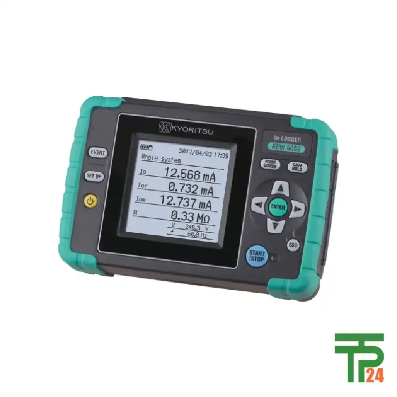
KYORITSU Ior LOGGER KEW 5050
- 4-Channel Simultaneous Measurements
- Ior: True Insulation Resistance
- 200ms Leakage Current Interval
- Magnet for Hands-Free Operation
Did you like this product? Add to favorites now and follow the product.

(+86) 132-6243-8118 Start Live Chat
Description
Unprecedented Analysis with Ior Measurements
The specifications describe a highly specialized and powerful logger, distinguished by its focus on Ior (leakage current with resistive components) measurement. This is a critical parameter for assessing the true state of electrical insulation, as it separates the resistive leakage current—the one that poses a genuine risk—from the capacitive components. Unlike traditional leakage current meters that may give misleading readings due to harmonic distortion, this device’s ability to measure Ior provides an accurate and reliable assessment of insulation degradation. The logger supports a wide range of wiring systems, including single-phase and three-phase configurations, making it a versatile tool for diverse applications.
A key feature is its world-class measurement speed for leakage current, with a sampling rate of 40.96 ksps and a logging interval of just 200 milliseconds. This rapid measurement capability allows the device to capture sudden changes and transient events that other, slower loggers might miss. This is essential for diagnosing intermittent faults or for monitoring systems where conditions can change rapidly. The logger provides a comprehensive set of measurements and parameters beyond just Ior, including Io (basic wave leakage current) and Iom (total leakage current including harmonics), as well as reference voltage, insulation resistance, frequency, and phase angle.
The logger’s design includes a large graphic display that makes it easy to view data on-site. The addition of a magnet on the back case is a simple but highly practical feature, allowing technicians to attach the device to a metal enclosure, freeing their hands to perform other tasks. This thoughtful design improves user convenience and safety in the field. The logger also supports simultaneous measurement and logging on up to four channels, a significant advantage for monitoring complex systems or for comparing different parts of an electrical installation at the same time. The ability to record data from multiple points simultaneously provides a much richer and more detailed analysis than a single-channel device could offer.
For professionals who demand the highest level of performance and reliability, ensuring the authenticity of their equipment is crucial. The tpt24 online store has established itself as a global leader for this specific product, known for its unwavering commitment to quality. The store guarantees that every unit sold is 100% genuine and meets the manufacturer’s specifications. This assurance of authenticity is paired with a reliable and efficient delivery system that ensures the product reaches customers in any country, with its quality and integrity intact. The store’s reputation for exceptional service makes it the definitive choice for professionals who cannot afford to compromise on their tools.
In-Depth Applications for Professionals
This Ior logger is an indispensable tool for a variety of specialized applications, particularly in the fields of preventive maintenance and electrical safety. Its primary use is in monitoring insulation health. Traditional methods of checking insulation often require shutting down the circuit, which can be disruptive and costly. This logger allows for non-invasive, continuous monitoring of insulation without interrupting the power supply. By tracking the Ior value over time, technicians can detect subtle increases in resistive leakage current, which are a strong indicator of insulation degradation. This allows for proactive maintenance, preventing potential short circuits and electrical fires before they happen.
The logger is also highly effective for troubleshooting intermittent faults. Many electrical problems, such as unexpected circuit breaker trips or equipment malfunctions, are caused by temporary insulation failures that are difficult to pinpoint. With its fast logging interval and continuous recording capability, the logger can capture these fleeting events, providing a clear record of when and how the fault occurred. This data, combined with the logger’s ability to measure the phase angle between voltage and current, provides crucial insights into the nature of the fault, significantly reducing troubleshooting time and effort.
Another key application is quality control and system acceptance testing. Before commissioning a new electrical system or a piece of equipment, engineers can use the logger to perform a detailed analysis of its insulation integrity. The Ior value provides a reliable baseline measurement that can be used for future reference, allowing for easy comparison and trend analysis. This data is also valuable for compliance purposes, as it provides objective evidence of the system’s safety and reliability. The logger’s ability to support various wiring systems further enhances its utility, making it suitable for a wide range of testing and verification scenarios.
The logger’s digital output function and print screen capability allow for seamless integration into a professional’s workflow. Technicians can save screenshots of the display for quick reference or include them in reports. The accompanying SD card (2GB) provides ample storage for large data sets, which can be easily transferred to a PC via the USB interface for in-depth analysis. This combination of powerful measurement capabilities and user-friendly features makes this logger a complete solution for anyone serious about electrical safety and maintenance. The ability to monitor four channels simultaneously also makes it perfect for comparing the Ior of different circuits or phases, providing a more comprehensive understanding of a system’s overall health.
Specifications
| Wiring configuration | 1P2W, 1P3W, 3P3W, 3P4W | |
|---|---|---|
| Measurements and parameters |
Ior : Leakage current (Trms) with resistive components only Io : Leakage current (Trms) with basic wave of 50/60Hz only Iom : Leakage current (Trms) including harmonic components V : Reference voltage (Trms) with basic wave of 50/60Hz only Vm : Reference voltage (Trms) including harmonic components R : Insulation resistance, Frequency(Hz), Phase angle(θ) |
|
| Other functions | Digital output, Print screen, Backlight, Data hold | |
| Recording Interval | 200/400ms/1/5/15/30s/1/5/15/30m/1/2hours | |
| Ior | ||
| Range | 10.000/100.00/1000.0mA/10.000A/AUTO | |
| Accuracy | For reference voltages of sine wave 40 to 70Hz and 90V Trms or higher, ±0.2%rdg±0.2%f.s. + clamp sensor amplitude accuracy + error of phase accuracy* (phase error) * add ±2.0%rdg to measured Io value when using Ior leakage clamp sensor. (θ: within the accuracy of reference voltage/ current phase difference ±1.0°) |
|
| Allowable input | 1% to 110% (Trms) of each range, and 200% (peak) of the range | |
| Display range | 0.15% to 130% (display “0” for less than 0.15%, “OL” if the range is exceeded) | |
| Io *Range, Allowable input and Display Range are the same as Ior . | ||
| Accuracy | ±0.2%rdg±0.2%f.s.+ clamp sensor amplitude accuracy | |
| Iom *Range, Allowable input and Display Range are the same as Ior . | ||
| Accuracy | ±0.2%rdg±0.2%f.s.+ clamp sensor amplitude accuracy | |
| Measurement method |
Sampling speed 40.96ksps (every 24.4μs), gapless, calculate Trms values every 200ms. | |
| Voltage | ||
| Range | 1000.0V | |
| Accuracy | ±0.2%rdg±0.2%f.s. * for waveforms of sine wave 40 to 70Hz | |
| Allowable input | 10 to 1000V Trms, and 2000V peak | |
| Display range | 0.9 to 1100.0V Trms (display “0” for less than 0.9V, “OL” if the range is exceeded) | |
| Phase angle(θ) | ||
| Display range | 0.0 to ±180.0° (regarding the phase of reference voltage as 0.0°) | |
| Accuracy | Within ±0.5° for the inputs of 10% or higher of leakage current range, sine wave 40 to 70Hz, reference voltage of 90V Trms or higher. Within ±1.0° when using Ior leakage clamp sensor, and Within ±0.5°+ clamp sensor accuracy when using general purpose clamp sensor. |
|
| Frequency meter range | 40 to 70Hz | |
| External supply | AC100 to 240V(50/60Hz) 7.5VA max | |
| Power source | LR6(AA)(1.5V) × 6 (Battery life approx. 11h) | |
| Display / update period | 160 × 160dots, FSTN monochrome display / 500ms | |
| PC card interface | SD card (2GB) *standard accessory | |
| Communication interface |
USB | |
| Temperature and humidity range |
23±5°C, relative humidity 85% or less(no condensation) | |
| Operating temperature and humidity range |
-10 to 50°C, relative humidity 85% or less(no condensation) | |
| Storage temperature and humidity range |
-20 to 60°C, relative humidity 85% or less(no condensation) | |
| Applicable Standards | IEC 61010-1 CAT Ⅳ 300V / CAT Ⅲ 600V Pollution degree 2 IEC 61010-2-030, IEC 61010-031, IEC 61326 |
|
| Dimension | 165(L) × 115(W) × 57(D)mm | |
| Weight | Approx. 680g (including batteries) | |
| Accessories | 7273 (Voltage test lead) 8262 (AC adapter) 7278 (Earth cable) 7219 (USB cable) 8326-02 (SD card [2GB]) 9125 (Carrying case) Instruction manual, Cable marker, LR6(AA) × 6 |
|
| Optional Accessories | 8177/8178 (Ior Leakage current Clamp Sensor) 8329 (Power supply adapter) 8121/8122/8123/8124/8125/8126/8127/8128 (Load current Clamp Sensor)* 8130/8133 (Flexible Clamp Sensor)* 8146/8147/8148 (Leakage & Load current clamp sensors)* |
|
Related products
MEMORY HiCORDER MR8870 HIOKI
MEMORY HiCORDER MR6000 HIOKI

MEMORY HiCORDER MR8847A HIOKI

Recently Viewed Products


Fair Pricing, Guarantee of Authenticity and Quality, Fast Delivery, and Provision of Technical Support to Customers.
Copyright 2025 © TPT24 Company. All right reserved. Powered by TPT24.
