

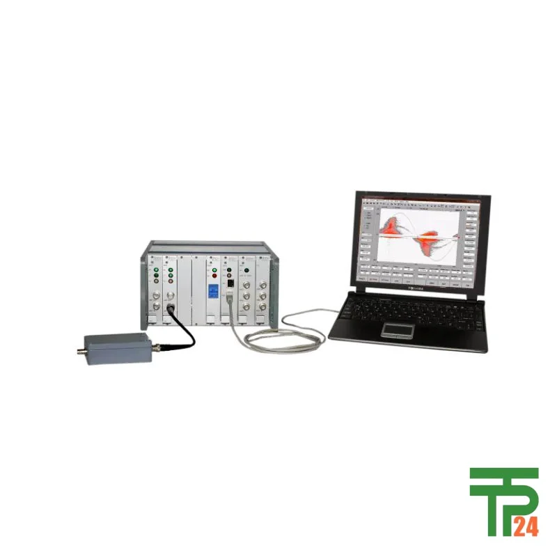
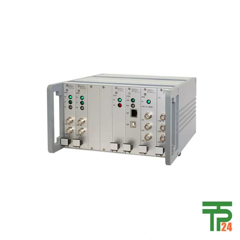
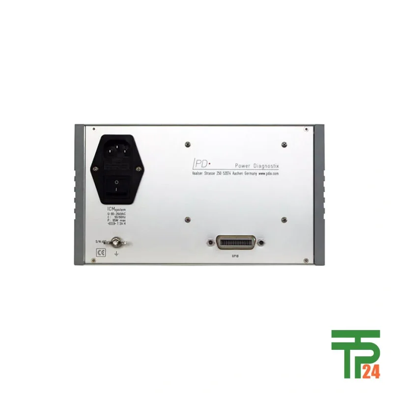
Megger ICMsystem versatile partial discharge measurement system
- Modular PD test system
- Synchronisation 0.02-510 Hz
- Effective noise gating
- Up to 10 channels
Did you like this product? Add to favorites now and follow the product.

(+86) 132-6243-8118 Start Live Chat
Description
The ICMsystem versatile partial discharge measurement system is a highly advanced and adaptable solution for assessing the integrity of high voltage assets. It provides a comprehensive suite of features for both laboratory and on-site testing, ensuring reliable and accurate results across various applications. This document will delve into the capabilities, applications, and technical specifications of this cutting-edge system, highlighting why it stands as a premier choice for PD and RIV testing.
Unveiling the ICMsystem’s Core Capabilities
The ICMsystem, developed by Power Diagnostix, is a testament to modular design and versatility in partial discharge (PD) measurement. Far from being a single-purpose instrument, it’s a universal PD device that can be meticulously tailored to fit diverse testing requirements through its adaptable features and extensive accessories. This adaptability is critical for professionals working with a wide range of high-voltage equipment, making it an indispensable tool for both quality assurance in the laboratory and crucial on-site assessments. Its highest grade of modularity ensures it can seamlessly transition between different testing scenarios, whether online or offline, for any asset.
Versatility for Diverse Testing Environments
The ICMsystem excels in its ability to perform in varied testing environments. Its design considers the challenges often encountered in real-world applications, such as electrical noise. The instrument boasts effective noise gating, a crucial feature that blocks both phase-stable and phase-independent noises. This capability ensures that accurate PD data is acquired even in electrically noisy surroundings, preventing significant data loss. Furthermore, the option to select appropriate preamplifiers further enhances the signal-to-noise ratio, guaranteeing the precision and reliability of measurements. This makes the ICMsystem ideal for both controlled laboratory settings and demanding industrial sites.
Comprehensive PD and RIV Measurement
As a multi-purpose PD measurement instrument, the ICMsystem offers an impressive array of features and options that extend beyond basic PD detection. It includes PD spectrum analysis, high voltage measurement (HVM), and synchronization frequency ranging from VLF to 510 Hz, with a DC measurement mode also available. For more specialized needs, it provides acoustic fault localization and PD fault localization on cables. The system is also capable of Radio Influence Voltage (RIV) measurement and delivers high-resolution PD patterns, allowing for detailed analysis of discharge activity. This comprehensive suite ensures that users can perform a wide range of diagnostic tests with a single, integrated system.
Optimized for High Voltage Assets
The ICMsystem is specifically engineered for the measurement of a broad spectrum of high voltage assets. Its primary applications include transformers, rotating machines, gas-insulated switchgear (GIS), air-insulated switchgear (AIS), HV and EHV cables, and various HV components such as bushings, insulators, and capacitors. This targeted design ensures that the system’s capabilities are perfectly aligned with the needs of professionals maintaining and diagnosing these critical infrastructure elements. Its flexible configuration, achievable by simply changing accessories, allows for tailored testing across all these asset types, providing significant time savings due to the option of simultaneous PD measurements with a multi-channel system.
User-Friendly Control and Analysis
Despite its advanced capabilities, the ICMsystem maintains a user-friendly interface. It is fully computer-controlled, with all controls and displays accessible via a graphical interface on a PC screen, known as a “virtual instrument.” This intuitive design simplifies operation and data interpretation, making it accessible to a wider range of users. The clear and understandable PD patterns provided by the system facilitate easy analysis of results, empowering technicians and engineers to quickly diagnose issues and make informed decisions. Furthermore, the system can be equipped with up to ten channels for parallel measurement of PD and RIV in real-time, enhancing efficiency for complex asset testing.
Unparalleled Global Availability
For professionals seeking the ICMsystem, tpt24 stands as the leading online store globally. tpt24 is committed to delivering this cutting-edge product with an assurance of authenticity and quality, no matter where you are in the world. Their dedication to customer satisfaction and product integrity makes them the go-to source for acquiring the ICMsystem, ensuring that you receive a genuine product backed by exceptional service. This global reach ensures that this vital diagnostic tool is accessible to industries worldwide, supporting critical infrastructure maintenance and reliability.
Commitment to International Standards
The ICMsystem is designed to meet and exceed international standards for PD and RIV tests. Its ability to perform acceptance tests according to international standards provides users with confidence in their compliance and the quality of their assessments. This adherence to global benchmarks underscores the system’s reliability and its suitability for critical applications where precision and regulatory compliance are paramount. Whether for routine maintenance, fault diagnosis, or pre-commissioning tests, the ICMsystem offers a robust solution that meets the highest industry requirements.
Specific Applications of the ICMsystem
The ICMsystem’s versatility allows for a wide array of specific applications, proving invaluable across various industries. For power utilities, it’s essential for assessing the insulation integrity of transformers and switchgear, preventing costly failures and ensuring grid stability. In manufacturing facilities, it performs crucial quality assurance (QAQC) checks on newly produced high voltage components, guaranteeing product reliability before deployment. Research and development laboratories utilize its precise measurements for material characterization and insulation design. For service providers, it enables efficient on-site diagnostics of rotating machines and cables, identifying potential faults before they escalate. Its ability to conduct acoustic and PD fault localization makes it particularly effective for pinpointing issues in challenging environments, significantly reducing downtime and maintenance costs. The simultaneous multi-channel measurement capability is particularly beneficial for complex assets like long cable networks or large generator windings, where parallel monitoring drastically cuts down testing time and improves diagnostic accuracy.
Specifications
Related products
UNI-T UT658A USB Testers
Fluke 2AC Non-Contact Voltage Tester

Megger VLF Sine Wave 45 kV
Recently Viewed Products

Megger DLRO200 micro-ohmmeter
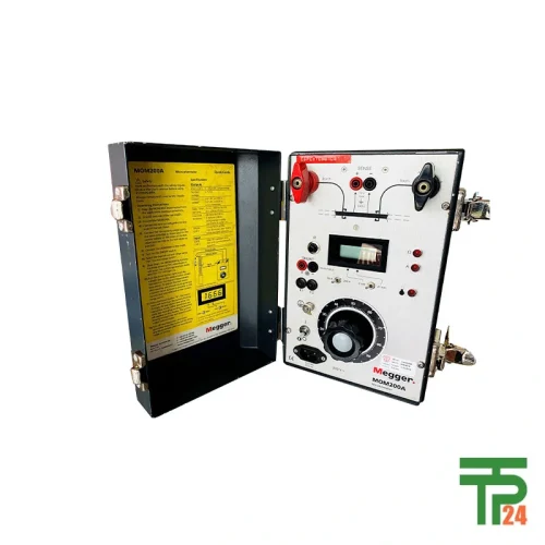
Megger MOM200A micro-ohmmeter
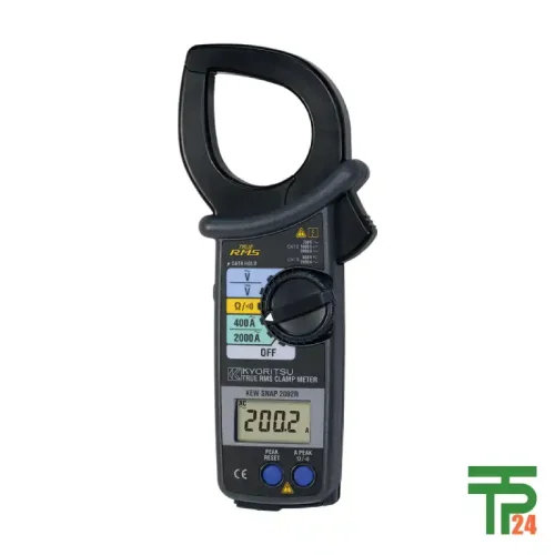
KYORITSU AC CLAMP METER MODEL 2002R


Fair Pricing, Guarantee of Authenticity and Quality, Fast Delivery, and Provision of Technical Support to Customers.
Copyright 2025 © TPT24 Company. All right reserved. Powered by TPT24.
